
Ground-fault overvoltage danger in modern unit-connected generators
M. Zielichowski, M. Fulczyk, R. Mydlikowski
Technical University of Wroclaw
Institute of Electrical Power Engineering (1-8 )
Wybrzeze Wyspianskiego 27, 50-370 Wroclaw, Poland
tel. 48 71 3203562 - fax 48 71 3203596
Abstract -
In this paper the ground-fault overvoltages in the circuits of unit-connected generators during interrupted arcing ground-faults in the stator winding of the generator with the neutral grounded through the ground-fault neutraliser were analysed. Comparative simulation tests of ground-fault voltages and currents for units with the biggest difference in parameters at the neutralisation coefficient equal to 0.6 were carried out. The currents in all the branches of the equivalent scheme of the unit, the voltage drops on its particular elements and the overvoltage dangers were determined. The real changes in the resistance of the ground-fault arc in the main insulation the stator windings and the real mechanism of its quenching were taken into account.
INTRODUCTION
In order to protect effectively unit-connected generators against the effects of ground-faults in their stator windings the phenomena that accompany these faults must be investigated fully. Overvoltages during arcing ground-faults close to the generator terminals the greatest danger to the main insulation of the generator windings pose [1,2]. Appropriately high overvoltages are accompanied by a significant increase in electrical stresses in the winding main insulation. These stresses weaken the insulation and can cause secondary faults.
Since the ground-fault arc has interrupted character, multiple ignitions and quenching accompanied by fast transients occur in the ground-fault process [3]. These phenomena have a marked influence on the ground-fault overvoltage values [4].
The voltage-current fast transients during ground-faults in the stator of the unit-connected generator depend on the parameters in its zero-sequence circuit and on the mechanism of the interrupted ground-fault [5]. This applies to mainly the elements grounding the generator neutral [7-10], the elements connected to its terminals, the resistance of the ground-fault are and the mechanism of its quenching [11].
In this paper the results of an extensive program of simulation tests of the voltage and current fast transients during arcing ground-faults in the stator of unit connected generators with the neutral grounded through the ground-fault neutraliser are presented. The currents in all the branches of the equivalent system scheme, and the voltage drops on its particular elements were determined and the ground-fault current overvoltage danger was analysed. In the analysis the real changes in the dynamic resistance of the ground-fault arc in the main insulation of the stator winding and the real mechanism of its quenching were taken into account.
Knowing that fast transients depend slightly on the neutralisation coefficient, a detailed comparative analysis for two unit-connected generators with the biggest difference in parameters at the neutralisation coefficient equal to 0.6 was carried out. On the basis of the numerical computations the influence of the unit parameters on the voltages and currents during arcing ground-faults in the stators o;
137.5 and 1110 MVA generators was determined.
MODEL AND DATA OF TESTED SYSTEM
The extent of the direct damage to the magnetic circuit and the main insulation of the generator stator winding caused by a ground-fault depends on the energy emitted in the ground-fault arc. Since this energy is determined by the value of the ground-fault current, the generator neutrals are grounded through the ground-fault neutraliser formed by a coil connected into the secondary winding of the distribution transformer. In this way the ground-fault current for this generator is limited to a safe value. Grounding through the ground-fault neutraliser allows one to obtain also the optimum operating conditions for ground-fault protections [14].
Figure l - One-line diagram of generator system into which ground-fault neutraliser has been incorporated.
A failure in the main insulation of the stator winding can occur at any place, including the generator neutral. It follows from the failure analysis of the unit connected generators that ground-faults occur more frequently in the second part of the winding counting from the generator neutral. Since, from the ground-fault overvoltages point of view, the faults close to the generator terminals are the most dangerous, these faults are analysed in this paper.
Ground-faults have always interrupted character independent of the causes of the breakdown in the main insulation of the stator windings. The properties of the ground-fault channel change with time. This is because the organic parts of the insulation carbonize at high temperatures.
The real changes in the dynamic arc ground resistance and the real mechanism of its burning are discussed in [2,3,11,13,14]. On the basis of these papers simulation tests of ground-fault overvoltages in the system shown in figure 2 were carried out.
Because it was found that the resistance's of the generator winding had an insignificant influence on the analysed phenomena, this parameter was neglected in the further analysis. The parameter values of the unit-connected generators assumed for the simulation analysis are listed in table 1.
In order to determine the influence of the unit-connected generator parameters on the ground-fault overvoltages, the simulation tests for the units with the biggest difference in parameters were carried out. This allows the full estimation of the overvoltage danger in actually operated units.

Fig.2. Simplified equivalent scheme of unit-connected generator used in analysis of voltage and current fast transients.
Parameters in this figure stand for:
CN
- 3/2 of phase capacitance of generator winding to ground;Ct
- 1/2 of phase capacitance of generator to ground;Cz
- equivalent capacitance to ground (Cz= Cp + CTb + CTV ):Cp
- equivalent phase capacitance of connection between generator and main transformer and unit auxiliarytransformer to ground,
CTb
- equivalent phase capacitance of main transformer to ground seen from the generator,CTV
- equivalent phase capacitance of unit auxiliary transformer to ground in generator terms,![]() =
=![]()
![]()
L’’ - subtransients generator inductance, counted as arithmetic average of direct-axis and quadratic-axis subtransient inductance in saturated conditions,
L0
- zero-sequence inductance of generator,R
- phase resistance of generator stator winding,Lk , Rk
- equivalent inductance and resistance of ground-fault neutraliser, respectively,ra
- dynamic resistance of ground-fault arc.
Table 1 - Parameters of unit connected generator
|
Generator power [MVA] |
137.5 |
1110 |
|
Voltage [kV] |
13,8 |
24 |
|
Cf [m F] |
0,196 |
0,210 |
|
Cz [m F] |
0,013 |
0,058 |
|
L" [mH] |
0,580 |
0,421 |
|
Lg [mH] |
-0,042 |
-0.071 |
ANALYSIS OF GROUND-FAULT OVERVOLTAGES
As a result of simulation tests the ground-fault voltages and currents in the fast transient, after the first arc ignition and in the whole ground-fault process were determined. The interrupted ground-fault was modelled on the generator terminals of the
R phase. The first breakdown occurred when the eR voltage reached a maximum. The obtained voltages and currents are given in relative units in relation to the Ufm amplitude of the eR generator phase voltage or a current value equal to Ufm *1W -1 respectively.The currents in the analysed scheme are calculated determined by applying the following system of equations:
iR = itR + izR + ia
iS = itS + izS
iT = itT + izT
ig = iN + iRk + iLk
The currents in the generator stator windings between the first arc ignition (t=0,05ms) and quenching (t=0,5ms), and then in the non-current break after arc quenching are shown in figures 3 and 4.
During fast transients after arc ignition the oscillatory component of particular phase currents is a sum of two currents with a frequency in the range from 15 to 40 kHz, but its values differ doubly. For example in 1110MVA generator these frequencies are equal to 20 and 40 kHz respectively. Depending on the type of a generator the maximum amplitude of the current oscillatory component changes from a few to several amperes, e.g. in an 1110MVA generator it approaches 15A. When arc is burning this current is dampened relatively fast and the oscillations practically decay till the arc quenching.

Figure 3 - R phase current and its components in generator circuits from generator terminals: a) 1110MVA, b) 137.5MVA.
After the arc quenching the amplitude of the oscillatory components of phase currents depends on the current value in the ground-fault channel at the moment preceding the arc quenching. The amplitude of the particular harmonics of these currents depends also on the parameters of the unit-connected generator. Since the resistances of the generator phase windings are negligible low and the resistance of the breakdown channel in the main insulation is equal to infinity, the oscillations are dampened very slowly.
As is shown in figure 5, the current transients in the ground-fault neutraliser after arc ignition increase with time. In comparison to the current value in the other branches of the scheme they arе negligible low.
The highest values of the current at the moment of arc quenching do not exceed a few percent of the amplitude of the current oscillatory component in the shorted phase. It follows that the parameters of the ground-fault neutraliser practically have no influence on the current transients during an arcing ground-fault in the generator stator. For this reason the current flowing from the generator neutral to ground-fault place through capacitance
cN is a sum of the phase currents.Comparing the current fast transients in both analysed generators it becomes apparent that from the overvoltage danger point of view the differences in the amplitude, the frequency and the damping coefficient are insignificant
The voltages on the L" inductance of the generator stator winding caused by flowing current oscillatory components equal maximally a few percent of the phase voltage both during the burning of the ground-fault arc and after its quenching (fig.6).

Figure 4 - S phase current and its components in generator circuits from generator terminals: a) 1110MVA; b) 137,5MVA
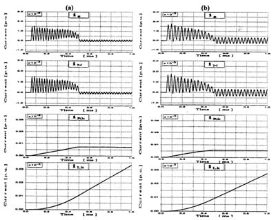
Figure 5 - Currents in circuits of unit from generator neutral side: a) 1110MVA, b) 137.5MVA
The oscillatory voltages in the fast transients do not pose the overvoltage danger to the main insulation of the generator. This is shown in figure 7 where the voltages in the fast transients between the generator terminals and the ground are presented. Because the fast transients voltages are similar in both generators, the conclusions can be applied to any actually operated unit-connected generators.
Figure 8 shows the voltages at the generator terminals to ground during the whole process of ground-fault, e.g. during successive arc ignitions and quenching and non-current breaks in the ground-fault channel. It has been found that the maximum values of ground-fault overvoltages do not exceed the double amplitude of the generator phase voltage and the differences in the parameters between particular generator types have an insignificant influence on these overvoltages.
The simulation tests showed that the voltage drop on the Lg inductance is negligibly low (fig. 9). This means that in the analysis of the voltage fast transients after ground-fault arc ignition the differences between parameters of the generator for particular sequence currents can be neglected.

Figure 6 - Voltages on subtranients L" inductance in generator: a) 1110MVA, b) 137.5MVA

Figure 7 - Fast transients of phase voltages in generator a) 1110MVA, b) 137.5MVA.

Figure 8 - Voltages during interrupted arcing ground-fault in generator a) 1110MVA; b) 137.5MVA
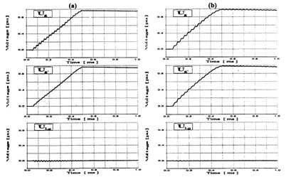
Figure 9 - Voltages of generator neutral a) 1110MVA; b) 137.5MVA
CONCLUSIONS
1. The oscillatory component of current fast transients in the windings of the generator stator after ground-fault arc ignition is a sum of the two oscillatory currents with a double difference in its frequency and it in ranges from a few to several kHz. These currents are dampened very fast and they practically decay between successive ignition and quenching.
2. The parameters of the ground-fault neutraliser have no significant influence on the fast transients in the circuits of the unit-connected generator during an arcing ground-fault in the stator winding of the generator.
3. The voltage drops in the windings of the generator caused by the oscillatory component of the current transient do not exceed a few percent of the amplitude of the generator phase voltage.
4. The difference in the parameters of the generator for the positive sequence of the subtransient current and for zero-sequence currents can be neglected in the analysis of the voltage fast transients during an arcing ground-fault.
5. The fast transients of the voltage after arc ignition do not pose danger to the main insulation of the windings of the unit-connected generator.
6. The difference in the parameters of particular unit-connected generators does not have a significant influence on the ground-fault overvoltage danger.
BIBLIOGRAPHY
[1] M-Zielichowski: Erosion du circuit magnetigue des stators de turbogeneraterus pendant les courts-circuits a la terre", Revue Electricity, Vol. DC, No. 12, pp.226-234, 1980,
[2] M.Zielichowski: Current-voltage transients in the breakdown channel during earth-faults in stator windings of turbogenerators, Archiwum Elektrotechniki, Vol.37, No. 1/4, pp. 141-147, 1988.
[3] M.Zielicfaowski: ,,Earth-fault transients in generator-transformer of 360MW", in Proceedings of the 4th International Symposium on Short-Circuit Carrents in Power Systems, A.I.M., Liege, pp.3.15.1-3.15.5, 1990.
[4] M-Zielichowski: ..Influence of turbogenerator neutral point grounding on overvoltages due to earth-faults", Archiwum Elektrotechniki, Vol.43, No. 1, pp. 123-138, 1994.
[5] M.N.Rajk: "Ground-fault protection of unit-connected generators", AIEE Transaction, pt.III, pp. 1082-1094, 1958.
[6] M.Zielichowski, M-Fulczyk: "Problems of the ground-fault overvoltages in generator-transformer unit", Szklarska Poreba, 14-16 May 1997, Scientific Papers of the Institute of Electric Power Engineering of the Technical University of Wroclaw,
№89, Conferences №32, pp.223-230, 1997[7] J.Basilesco, J.Taylor: "Report on methods for earthing of generator step-up transformer and generator winding neutrals as practised throughout the word", CIGRE, No. 121, pp.86-101,1988.
[8] E.M.Gulachenski, E.W.CourviUe: "New England electric's 39 years of experience with resonant neutral-grounding of unit-connected generators", IEEE Transients on Power Delivery, Vol.6, No.3, pp.1016-1024, 1991;
[9] A.C.Pierce: Generator ground protection guide, IEEE Transaction on Power Apparatus and Systems, Vol.PAS-03, No 7, pp. 1743-48, 1984.
[10] H.R.Tonulinson: "Ground-fault neutralizer grounding of unit-connected generators", AIEE Transaction, Vol.72, pt.III, pp.953-960, 1953.
[11] M.Zielichowski: "Mechanism of ertc-fault are quenching in the main isolation of the turbogenerators", in Proceedings of the first European Conference on Power Systems Transients, Institute da Energia INTERG, Lisbon. pp.33-38. 1993.
[12] M.Zielichowski: "Optymization of third harmonic ground fault protection scheme for unit connected generators", in Proceedings of the International Power Engineering Conference IPEC'95, Nanyang Technology University, Singapore, pp.323-327,1995.
[13] M.Zielichowski, M.Fulczyk: "Ground-fault fast transients in the generator stator windings", Ninth International Symposium on High Voltage Engeenering ISH'95, Institute of High Voltage Eng. Graz University of Technology, Graz, Vol.6, pp.6796-1 -6796-4, 1995.
[14] M.Zielichowski, M.Fulczyk: "Influence of neutralizer on ground fault overvoltages in generator stator windings", in Proceedings of the second European Conference on Power Sysytems Transients, Institute da Energia INTEG, Lisbon, pp.33-38, 1995.