
GROUP: ТТR - 00b
FAKULTY: Mining and geology faculty
THEME OF MASTER'S WORK: "Exploration of Statistical Contact Tension in the Time of Interaction of Balls with Details of Coordinating Device of Pulsation-pump"
SCEINTIFIC SUPERVISER: Candidate of engineering sciences Filimonenko Nikolay Tiverievich
oleyniktanya@rambler.ru oleyniktanya@rambler.ru
 Автореферат
|
|
INTERNET SEARCH RESALTS | LIBRARY | BIOGRAPHY
|
The technology of drilling with pulsating washing inside a bore-hole that is created by immersing pneumatic displacer is known. During its realization in the bore- hole the level of washing liquid is keeping up to reduce its absorption to minimum.
Exploitation of immersing pneumatic pulsation displacer and immersing air distributor showed that practically all faults during work of the device were caused because the main details of the system valve-block of an air distributing mechanism were wedged. Visual check up showed inadmissibly fast wear and tear of details contacting with the fixative balls. Besides it, presence of plastic deformations such as rivet in the places of contact witnesses about their striking origin. The main aspect of improving the reliability of pneumatic displacer and immersing air distributor is profound study of movement of details of system valve-block during the work of device that allows to forecast loading in the places of their contact with fixative balls and gives the opportunity to recommend constructive peculiarities of details which are mostly subjected to wear-out.
Review of Existing
Developments
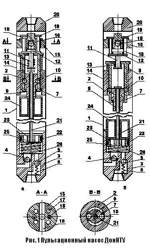
The pulsation-pump goes down into the bore-hole with a boring gear. During it through the valve 4 the liquid fills the inner part of the pump body 1 that is a displacing chamber. A float-valve 24 takes the upper position (picture 1a), because it is lighter than liquid. Thus at the point of departure an exhaust valve 19 is opened. An exhaust valve 12 is closed (owing to the operation of spring 8). The float-valve 24 rests on trigger valve 9.
The pump works the following way. During supplying into boring pipes of compressor air goes through the bore-hole in the transitional device 20, channels 17 in the valve box 15, the gap between nipple 2 and the block 7 into inner part of the body 1, washing liquid is displaced on a face of the hole through a force-valve 5. The float valve 24 goes down with liquid and closes axial holes 25 of a sucker. Passing of air through the holes 25 stops. Pressure in the displacing chamber starts growing. Under influence of compressed air the sucker 22 goes down with traction 21, a trigger valve 9, a block 7 and fixative balls 10. Movement of the sucker 22 and block 7 down causes compression of springs 26 and 8. And valves 12 and 19 stay in the upper position owing to pressure of compressed air upon the valve 12 from down part.
Moving down the fixative balls 10 reach conic boring of the nipple 2 and enter it. The trigger valve 9 is released and then under influence of the traction 21 moves down to stop into bottom burtikes of the block 7 (picture 1b). Movement of the block 7 under influence of the sucker 22 continues to move when it compresses a valve spring 13 by its inner burtikes.
Transposition of the valves 12 and 19 of the air distributing mechanism to the bottom position takes place when compression power of the spring 13 becomes higher than pressure of compressed air upon the valve 12. The inlet valve 19 closes and the outlet 12 opens and connects the displacing chamber with atmosphere through the outlet window 16. Pressure in it reduces. As pressure in the displacing chamber is reducing, the chamber is being filling in through the suction-valve 4 owing to hydrostatic pressure of liquid column in the hole. The spring 26 releases and brings the sucker 22 and the traction 21 back to the upper point of departure. The float-valve with liquid 24 comes to the surface, rests against the bottom butt-end of the valve 9, and moves it up. The conic turner of the valve 9 is combined with the fixative balls 10. The balls enter the boring and release the block 7, that moves up under influence of the compressed spring 8. During movement the block 7 moves the valves 12 and 9 to the point of departure. The valve12 closes the outlet channel 16, and the valve 19 opens inlet channels 17. Thus the working cycle of the pump finishes.
Disadvantages of the pump:
• Exhaust of compressed air will be not into atmosphere, but under the liquid level. As a result of it both the time of fulfilling of the displacing chamber and irregularity of supply arise;
• After fulfilling the displacing chamber liquid goes to the boring pipes situated upper than the pump does. As a result of it power of pressure of compressed air upon liquid goes down when it is being displacing from the boring pipes.
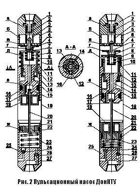
The following construction of the pulsation pump was the construction developed in the Mining Institute of Donetsk National Technical University in the department of Technology and Technic of Geological Prospecting in 1981. The challenge was to avoid the disadvantages of construction. The aim was reached by supplying the bottom butt-end of the trigger valve 14 with the sucker element 15, installed in the working cavity above the float-valve.
Practice of usage of this construction of the pulsation pump showed that after comparatively not a long time of its working the local plastic deformation such as rivet appeared on the details of system valve-block of air distributing mechanism. And level of deformation development is not the same on all the details. The reason of it is multipoint dynamic and steady - state contacts of steel fixative balls 12 of high hardness with above named main details of air distributing mechanisms. Development of plastic deformation quite often led to wedging of the fixative balls and to failure of mechanism. Visual control of unserviceable details let us to reveal only the places of deformation localization. Actual are projects directed on increasing of device reliability.
The construction of the pump consists of a two-valve air distributing mechanism, a coordinating device and the pump itself gathered in one body.
The air distributing mechanism includes an exhaust valve 7, the tail 9 and the spring 8 of which is situated in the central valve of the block 13 and the exhaust valve 4, that is in the central hole of the valve box 6, that is connected with upper transitional device 1 with inner 3 and out 5 branch pipes. There is an air filter 2 in the upper transitional device 1. The coordinating device includes leaning on the spring 11 block 13, connected with fixative balls 12 and with trigger valve 14, firmly connected with the sucker 15, that is situated in the central channel of the nipple 16. The pump part is formed by the valve box 25 with holes for the suction-valve 24 and the force-valve 26.
The connecting section between the pump part and the coordinating device is the float-valve 18, slithering on traction 20 and interacting with suckers 15 and 22. The air distributing mechanism, the coordinating device and the pump part are connected by the upper 10 and bottom 19 branch pipes.
Advantages of Developed Mechanism
In contrast to previous construction transaction of the trigger valve is realized by functioning on the sucker element power of hydrostatic pressure of liquid column, that is significantly higher than pushing power of the float-valve. That is why reliable switching is guaranteed and effectiveness of work of the pump improves.
The List of the Problems
Solved in the Work
The master’s thesis work represents a part of research work on the creation of technical devices for drilling of wells in abnormal conditions carried out by the Department of Technology and Principles of Geological Exploration.
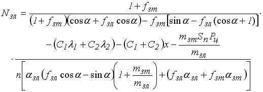
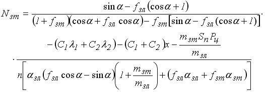
For the first time dynamic of elements of system the valve-block of pneumatic displacer was described. The formula for predicting efforts was obtained.
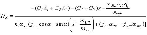
Rational value of angle a when advantageous for uniform wear and tear commensurability and minimization of tension in places of contact of the fixative balls with details of the system the valve-block under steady-state loading is 78˚С .
Results of calculation of the parameters q0, max t, max o under influence of the highest normal pressure of the fixative ball upon contacting with it surface of the nipple, the valve and the block when the angle a=78˚С are in the table 1.
Table 1
Value of q, max, max under influence of the highest normal pressure of the fixative ball upon contacting with it surface of the nipple, the valve and the block
|
|
|
|
|
|
|
|
|
|
|
|
|
|
|
|
|
|
|
|
In perspective it is possible to explore not only steady-state loading but percussive one, which we can observe during work of the pulsation pump.
Received recommendations concerning parameters of the construction were taken into account in construction documentation for the pulsation pump. The documentation is being prepared to be sent to the customer.
|
|
INTERNET SEARCH RESALTS | LIBRARY | BIOGRAPHY
|