
Full version of the article (original): http://www.lmphotonics.com/m_start.htm
Traditional Electromechanical Starters (LM Photonics Ltd)
short version
A.C. Induction motors are traditionally started and stopped by applying and removing the A.C. supply. In some cases, a full voltage start is acceptable, but in many situations, the start current must be reduced, and so a reduced voltage starter is employed.
1) Direct On Line
The simplest form of motor starter for the induction motor is the Direct On Line starter. The DOL starter comprises a switch and an overload protection relay.
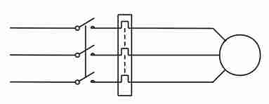
Figure 1 - DOL starter for the induction motor
The switch may be a manually operated load break switch, but more commonly it would be an electromagnetic contactor which can be opened by the thermal overload relay. Typically, the contactor will be controlled by separate start and stop buttons, and an auxiliary contact is used as a hold in contact. i.e. the contactor is electrically latched closed while the motor is operating.
To start, the contactor is closed, applying full line voltage to the motor windings. The motor will draw a very high inrush current for a very short time, to establish the magnetic field in the iron, and then the current will be limited to the Locked Rotor Current of the motor. The motor will develop Locked Rotor Torque and begin to accelerate towards full speed. As the motor accelerates, the current will begin to drop, but will not drop significantly until the motor is at a high speed, typically about 85% of synchronous speed. The actual starting current curve is a function of the motor design, and the terminal voltage, and is totally independent of the motor load. The motor load will affect the time taken for the motor to accelerate to full speed and therefore the duration of the high starting current, but not the magnitude of the starting current.
Provided the torque developed by the motor exceeds the load torque at all speeds during the start cycle, the motor will reach full speed. If the torque delivered by the motor is less than the torque of the load at any speed during the start cycle, the motor will cease accelerating. If the starting torque with a DOL starter is insufficient for the load, the motor must be replaced with a motor which can develop a higher starting torque. The acceleration torque is the torque developed by the motor minus the load torque, and will change as the motor accelerates due to the motor speed torque curve and the load speed torque curve. The start time is dependant on the acceleration torque and the load inertia.
DOL starting results in maximum start current and maximum start torque. This may cause an electrical problem with the supply, or it may cause a mechanical problem with the driven load.
Figure 2 - Characteristics of the induction motor DOL start
2) Primary Resistance
The Primary Resistance starter will have one or more sets of resistors which, during start, are connected in series with the supply to the motor. The series resistors limit the starting current drawn by the motor, and thus reduce the starting torque of the motor.
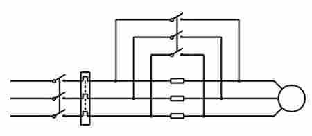
Figure 3 - Primary resistance starter for the induction motor
Once the motor is up to full speed (or after a period of time) the resistors are bridged by a contactor to apply full voltage to the motor. If the full details of the motor starting characteristics are known, and the starting characteristics of the load are also known, it is practical to determine the correct value of the resistors to provide enough start torque for the load while minimizing the starting current. A primary resistance starter correctly designed and constructed, will cause the motor to accelerate the load to almost full speed with the resistors in circuit before they are bridged out. In this case, the transition to full voltage only occurs once the impedance of the motor has risen, and the resulting current is much less than the LRC of the motor. In a poorly designed system, the transition to full voltage will occur at less than 80% full speed, and the current will then step up to almost DOL current, resulting in little gain from the use of the primary resistance starter other than the increased cost of the starter. (advantageous to the starter supplier, not to the end user.) Improved starting characteristics with some loads can be achieved by the use of several stages of resistance and bridging out increasing amounts of resistance as the motor accelerates.
With the primary resistance starter, it is not easy to alter the resistance and hence the starting characteristics once the starter is built. Therefore, it is important that the correct resistors are selected in the first place.
The primary resistance starter reduces the voltage applied to the motor terminals while passing the full starting current to the motor. Consequently, there is a very high power dissipation in the resistors, resulting in the requirement for very high power rated resistors. Typically, the resistors will dissipate as much as 150% - 200% the power rating of the motor for the duration of the start.
The resistors may be either metallic resistors, or liquid resistors. Metallic resistors have a positive temperature coefficient and as a result, as they heat up, their resistance increases. Liquid resistors, such as saline solution, have a negative temperature coefficient and so consequently, as they heat up, their resistance reduces.
The heat build up in the resistors during start, and their temperature dependant resistance characteristics, make it essential the resistors are allowed to fully cool between starts. This restricts the starting frequency and the minimum time between the starts.
Figure 4 - Characteristics for start with the primary resistance starter
3) Primary Reactance
A Primary reactance starter is similar to a primary resistance starter except that the resistors are replaced by a three phase reactor to limit the starting current. The operation of the primary reactance starter is essentially the same as that of the primary resistance starter, but the use of a three phase reactor in place of the resistors offers the advantage of reduced heat loss and greater ease of start current setting due to the ability to change taps on the reactor.
4) Auto transformer
An Auto transformer starter uses an auto transformer to reduce the voltage applied to a motor during start. The auto transformer may have a number of output taps and be set-up to provide a single stage starter, or a multistage starter. Typically, the auto transformer would have taps at 50%, 65% and 80% voltage, enabling the motor to be started at one or more of these settings.
There are two ways of connecting an auto transformer starter, the most obvious way is to apply full voltage to the transformer via a contactor, and connect the motor to the tap by means of a contactor. When the motor has accelerated to full speed, or has run out of acceleration torque, the tap contactor opens, disconnecting the motor from the transformer and another contactor closes connecting the motor to the supply. The transformer can now be disconnected from the supply. This format is known as an open transition starter and is less than ideal due to the fact that the motor is disconnected for a short period of time during the start period. While the motor is connected and accelerating, there is a rotating magnetic field in the stator which causes flux in the rotor and thus a rotor current to flow. At the instant the motor is disconnected, there is a magnetic field in the rotor which is spinning with-in the stator winding. The motor acts as a generator until the rotor field decays. The voltage generated by the motor is not synchronised to the supply, and so on reconnection to the supply, the voltage across the contactor at closure can be as much as twice the supply voltage resulting in a very high current and torque transient.
By a rearrangement of the power circuit, it is possible, at no extra cost, to build a closed transition starter and thereby eliminate the current and torque transients. The closed transition auto transformer starter is known as the Korndorffer starter. The open transition switching is achieved by reconnecting the tap contactor between the transformer and motor, to the star connection of the transformer, hard wiring the motor to the tap, and altering the sequence of contactor control. To start the machine, the main contactor and the star contactors are closed applying reduced voltage to the motor. When the motor has reached full speed, (or run out of acceleration torque) the star contactor is opened effectively converting the auto transformer starter into a primary reactance starter. Next the primary reactance is bridged by a contactor applying full voltage to the motor. At no time does the motor become disconnected from the supply.
The transformer is generally only intermittent rated for the starting duty, and so the frequency and duration of the starts is limited. With a transformer starter, it is relatively easy to change taps and thereby increase the starting voltage if a higher torque is required. The auto transformer starter is a constant voltage starter, so the torque is reduced by the voltage reduction squared over the entire speed range, unlike the primary resistance or primary reactance starters which are constant impedance starters and where the start voltage is dependant on the ratio of the motor impedance to the motor plus starter impedance. As the motor accelerates, it's impedance rises and consequently, the terminal voltage of the motor also rises, giving a small torque increase at higher speeds.
Unlike the primary resistance and primary reactance starter, the current flowing into the motor is different from that flowing from the supply. The supply current flows into the primary circuit of a transformer, and the secondary current is applied to the motor. The transformer reduces the primary current by the same ratio as the voltage reduction. If the motor is connected to the 50% tap of the transformer, the voltage across the motor terminals will be 50%. Assuming an LRC of 600%, there will be 300% current flowing into the motor. If 300% current flows into the motor, then the current into the transformer will be 150%. This would suggest that the lowest starting current will be achieved by the use of an auto transformer starter. In most instances, the load will require an increasing torque as it accelerates, and so often a higher tap must be selected in order to accelerate the load to full speed before the step to full voltage occurs. If a multistage transformer starter is employed, then the primary current will certainly be lower than other forms of induction motor starter.
5) Star Delta
The Star Delta starter can only be used with a motor which is rated for connection in delta operation at the required line voltage, and has both ends each of the three windings available individually. At Start, the line voltage is applied to one end of each of the three windings, with the other end bridged together. Under this connection, the voltage across each winding is 1/v3 of line voltage and so the current flowing in each winding is also reduced by this amount. The resultant current flowing from the supply is reduced by a factor of 1/3 as is the torque, i.e. а motor which exhibits a LRC of 600% and an LRT of 180% will exhibit characteristics of: LRCstar of 200% and LRTstar of 60%. In some cases, this may be enough to get the motor up to full speed, but most, as this is a constant voltage starter, the transition to full voltage will occur at part speed resulting in a virtual DOL type start. Тhe star connection is opened, effectively open circuiting the motor, and the ends of the windings are then connected to the three phase supply in a fashion to create a delta connection. This type of starter is open transition starter. The star delta is not easily converted to a closed transition starter, and even the closed transition (Wanchop) star delta starter still has the problem that the start voltage can not be altered. If there is insufficient torque available in star, then it will go DOL. The star delta starter is used when there is a requirement for a reduced voltage starter, but in reality, in many situations results in more severe transients than DOL. The main benefits of the star delta starter are that it puts more money in the pockets of the switchgear supplier, and it is politically correct.
6) Slip Ring Motors
The Slip Ring motor is essentially similar to the standard cage induction motor except that the winding on the rotor has far more turns and instead of being short circuited, is brought out to a set of slip rings for external connection.
The operation of the slip ring motor is the same as that of the standard cage induction motor in that torque is generated by the interaction of the stator field and the rotor field. The rotor field being generated by current flowing in the rotor which is caused by the slip between the rotor and the stator field. The torque speed curve and the current speed curve can be altered by the rotor winding termination. A very high value of resistance on the rotor termination will give a very low locked rotor current, and a low locked rotor torque. Reducing the termination resistance, will increase both the locked rotor current and the locked rotor torque up to the point where maximum torque is available under locked rotor conditions. Further reduction of termination resistance will reduce the locked rotor torque by shifting the maximum (Pull Up) from zero speed towards synchronous speed. A short circuit across the rotor will result in the maximum torque occurring at a very low slip, and a locked rotor current as high as 1400% for a locked rotor torque of as low as 50%. It is imperative that there must be resistance in the rotor circuit of a slip ring motor during start if any starting torque is to be developed at a realistic starting current.
The slip ring starter comprises an isolation contactor for the stator circuit, and a series of rotor resistors and contactors controlled by a sequencer. The total power dissipated in the resistors will be at least equal to the kinetic energy of the driven load at full speed.
Slip ring motors typically have an open circuit rotor voltage of between 400 volts and 500 volts to keep the current to a manageable level.
The major disadvantage of the slip ring motor is that the ring gear suffers wear and requires regular maintenance, as does the starter, particularly if an electromechanical sequencer is used.