|
DonNTU>
Master's portal
Čńňî÷íčę://W. Bolton. Mechatronics. 2003., p. 17-22
Your body temperature, unless you are ill, remains almost constant regardless of whether you are in a cold or hot environment. To maintain this constancy your body has a temperature control system. If your temperature begins to increase above the normal you sweat, if it decreases you shiver. Both these are mechanisms which are used to restore the body temperature back to its normal value. The control system is maintaining constancy of temperature. The system has an input from sensors, which tell it what the temperature is and then compares this data with what the temperature should be and provides the appropriate response in order to, obtain the required temperature. This is an example of feedback control; signals are fed back from the output, i.e. the actual temperature, in order to modify the reaction of the body to enable it to restore the temperature to the 'normal' value. Feedback control is exercised by the control system comparing the fed back actual output of the system with what is required and adjusting its output accordingly. One way to control the temperature of centrally heated house is for a human to stand near the furnace on/off switch with a thermometer and switch the furnace on or off according to the thermometer reading. That is a crude form of feedback control using a human as a control element. The term feedback is used because signals are fed back from the output in order to modify the input. The more usual feedback control system has a thermostat or controller which automatically switches the furnace on or off according to the difference between the set temperature and the actual temperature. This control system is maintaining constancy of temperature. If you go to pick up a pencil from a bench there is a need for you to use a control system to ensure that your hand actually ends up at the pencil. This is done by you observing the position of your hand relative to the pencil and making adjustments in its position as it moves towards the pencil. There is a feedback of information about your actual hand position so that you can modify your reactions to give the required hand position and movement. This control system is controlling the positioning and movement of your hand. Feedback control systems are widespread, not only in nature and the home but also in industry. There are many industrial processes and machines where control, whether by humans or automatically, is required. For example, there is process control where such things as temperature, liquid level, fluid flow, pressure, etc. are maintained constant. Thus hi a chemical process there may be a need to maintain the level of a liquid in a tank to a particular level or to a particular temperature. There are also control systems, which involve consistently and accurately positioning a moving part or maintaining a constant speed. This might be, for example, a motor, designed to run at a constant speed or perhaps a machining operation in which the position, speed and operation of a tool is automatically controlled. Open- and closed-loop systems There are two basic forms of control system, one being called open loop and the other closed loop. The difference between these can be showed by a simple example. Consider an electric fire which has a selection switch which allows a 1 kW or a 2 kW heating element to be selected. If a person used the heating element to heat a room, he or she might just switch on the 1 kW element if the room is not required to be at too high a temperature. The room will heat up and reach a temperature which is only determined by the fact the 1 kW element was switched on and not the 2 kW element. If there are changes in the conditions, perhaps someone opening a window, there is no way the heat output is adjusted to compensate. This is an example of open-loop control in that there is no information fed back to the element to adjust it and maintain a constant temperature. The heating system with the heating element could be made a closed-loop system if the person has a thermometer and switches the 1 kW and 2 kW elements on or off, according to the difference between the actual temperature and the required temperature, to maintain the temperature of the room constant. In this situation there is feedback, the input to the system being adjusted according to whether its output is the required temperature. This means that the input to the switch depends on the deviation of the actual temperature from the required temperature, the difference between them determined by a comparison element - the person in this case. To show further the difference between open- and closed-loop systems, consider a motor. With an open-loop system the speed of rotation of the shaft might be determined solely by the initial setting of a knob which affects the voltage applied to the motor. Any changes in the supply voltages, the characteristics of the motor as a result of temperature changes, or the shaft load will change the shaft speed but not be compensated for. There is no feedback loop. With a closed-loop system, however, the initial setting of the control knob will be for a particular shaft speed and this will be maintained by feedback, regardless of any changes in supply voltage, motor characteristics or load. In an open-loop control system the output from the system has no effects on the input signal. In a closed-loop control system the output dose have an effect on the input signal, modifying it to maintain an output signal at the required value. Open-loop systems have the advantage of being relatively simple and consequently low cost with generally good reliability. However, they are often inaccurate since there is no correction for error. Closed-loop systems have the advantage of being relatively accurate in matching the actual to the required values. They are, however, more complex and so more costly with a greater chance of breakdown as a consequence of the greater number of components. Basic elements of a closed-loop system The general form of a basic closed-loop system consists of the following elements(fig. 1):
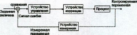 Figure 1 -The elements of a closed-loop control system With the closed-loop system illustrated in Figure 1 for a person controlling the temperature of a room, the various elements are:
An automatic control system for the control of the room temperature could involve a temperature sensor, after suitable signal conditioning, feeding an electrical signal to the input of a computer where it is compared with the set value and an error signal generated. This is then acted on by the computer to give at its output a signal, which, after suitable signal conditioning, might be used to control a heater and hence the room temperature. Such a system can readily be programmed to give different temperatures at different times of the day. 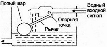 Figure 2- The automatic control of water lever Figure 2 shows an example of a simple control system used to maintain a constant water level in a tank. The reference value is the initial setting of the lever arm arrangement so that it just cuts off the water supply at the required level. When water is drawn from the tank the float moves downwards with the water level. This causes the lever arrangement to rotate and so allows water to enter the tank. This flow continues until the ball has risen to such a height that it has moved the lever arrangement to cut off the water supply. It is a closed-loop control system with the elements being:
The above is an example of a closed-loop control system involving just mechanical elements. We could, however, have controlled the liquid level by means of an electronic control system. We thus might have had a level sensor supplying an electrical signal, which is used, after suitable signal conditioning, as an input to a computer where it is compared with a set value signal and the difference between them, the error signal, then used to give an appropriate response from the computer output. This is then, after suitable signal conditioning, used to control the movement of an actuator in a flow control valve and so determine the amount of water fed into the tank. Figure 3 shows a simple automatic control system for the speed of rotation of a shaft. A potentiometer is used to set the reference value, i.e. what voltage is supplied to the differential amplifier as the reference value for the required speed of rotation. The differential amplifier is used to both compare and amplify the difference between the reference and feedback values, i.e. it amplifies the error signal. The amplified error signal is then fed to a motor, which in turn adjusts the speed of rotating shaft. The speed of the rotating shaft is measured using a tachogenerator, connected to the rotating shaft by means of a pair of bevel gears. The signal from the tachogenerator is then fed back to the differential amplifier. 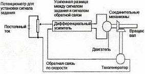 Figure 3 - Shaft speed control Sequential controllers There are many situations where control is exercised by items being switched on or off at particular preset times of values in order to control processes and give a step sequence of operations. For example, after step 1 is complete then step 2 starts, when step 2 is complete then step 3 starts, etc. The term sequential control is used when control is such that actions and strictly ordered in a time of event driven sequence. Such control could be obtained by an electrical circuit with sets of relays or cam-operated switches, which are wired up in such a way as to give the required sequence. Such hard-wired circuits are now more likely to have been replaced by a microprocessor-controlled system, with the sequencing being controlled by means of a software program. As an illustration of sequential control, consider the domestic washing machine. A number of operations have to be carried out in the correct sequence. These may involve a pre-wash cycle when the clothes in the drum are given a wash in cold water, followed by a main wash cycle when they are washed in hot water, then a rinse cycle when the clothes are rinsed with cold water a number of times, followed by spmning to remove water from the clothes. Each of these operations involves a number of steps. For example, a pre-wash cycle involves opening a valve to fill the machine drum to the required level, closing the valve, switching on the drum motor to rotate the drum for a specific time, and operating the pump to empty the water from the drum. The operating sequence is called a program, the sequence of instructions in each program being predefined and 'built' into the controller used.Figure 4 shows the basic washing machine system and gives a rough idea of its constituent elements. The system that used to be used for the washing machine controller was a mechanical system, which involved a set of cam-operated switches, i.e. mechanical switches. Figure 4 shows the basic principle of one such switch. When the machine is switched on, a small electric motor slowly rotates its shaft, giving an amount of rotation proportional to time. Its rotation turns the controller cams so that each in turn operates electrical switches and so switches on circuits in the correct sequence. The contour of a cam determines the time at which it operates a switch. Thus the contours of the cams are the means by which the program is specified and stored in the machine. The sequencer of instructions and the instructions used in a particular washing program are determined by the set of cams chosen. With modern washing machines the controller is a microprocessor and the program is not supplied by the mechanical arrangement of cams but by a software program. 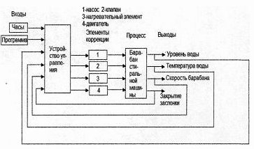 Figure 4 - Washing machine system For the pre-wash cycle an electrically operated valve is opened when a current is supplied and switched off when it ceases. This valve allows cold water into the drum for a period of time determined by the profile of the cam or the output from the microprocessor used to operate its switch. However, since the requirement is a specific level of water in the washing machine drum, there needs to be another mechanism which will stop the water going into the tank, during the permitted time, when it reaches the required level. A sensor is used to give a signal when the water level has reached the preset level and give an output from the microprocessor, which is used to switch off the current to the valve. In the case of a cam-controlled valve, the sensor actuates a switch, which closes the valve admitting water to the washing machine drum. When this event is completed the microprocessor, or the rotation of the cams, initiates a pump to empty the drum. For the main wash cycle, the microprocessor gives an output, which starts when the pre-wash part of the program is completed; in the case of the cam-operated system the cam has a profile such that it starts in operation when the pre-wash cycle is completed. It switches a current into a circuit to open a valve to allow cold water into the drum. This level is sensed and the water shut off when the required level is reached. The microprocessor or cams then supply a current to activate a switch, which applies a larger current to an electric heater to heat the water. A temperature sensor is used to switch off the current when the water temperature reaches the preset value. The microprocessor or cams then switch on the drum motor to rotate the drum. This will continue for the time determined by the microprocessor or cam profile before switching off. Then the microprocessor or a cam switches on the current to a discharge pump to empty the water from the drum. The rinse part of the operation is now switched as a sequence of signals to open valves, which allow cold water into the machine, switch it off, operate the motor to rotate the drum, operate a pump to empty the water from the drum, and repeat this sequence a number of times. The final part of the operation is when the microprocessor or a cam switches on just the motor, at a higher speed than for the rinsing, to spin the clothes. DonNTU> Master's portal> |