ƒонЌ“”>
ѕортал магистров ƒонЌ“”
Ѕиографи€ магистра: RUS |
UKR |
ENG | ћатериалы по теме выпускной работы: јвтореферат | Ѕиблиотека |
—сылки |ќтчет о поиске | »ндивидуальное задание
 antillesvedg2006@rambler.ru
12. Department of Mechanical, Materials and Aerospace Engineering // Final project: pulley puller.
(Subset)
( http://www-mae.engr.ucf.edu/eml4535/samplefinal.pdf )
FINAL PROJECT: PULLEY PULLER
Introduction:
It is very difficult in general to remove objects mounted on a shaft eg: , pulleys, gears, pinions, couplings, sheaves, bearing housings .It often turns out to be a task requiring more than one person. But by the use of Pulley pullers removing an object from a shaft become an easy task for just one person, which is an almost impossible using hand tool. The pulley puller removes objects from shafts with ease.
FEM model of the pulley puller will be model using shell elements for the left arm and the beam elements for the other arm and preload bolt and other-core will be modeled with linear tetras. Load of 5000 lbs will be applied to the preload bolt in +Y direction and required restraints will be applied to transmit the load and to avoid the possibility of a 3-bar mechanism. Fem model will be assembled using the append command.
Description of Pulley Puller
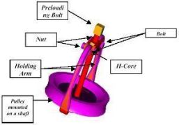
The basic pulley puller consists of mainly following components:
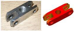
Holding arm: This is the main component of the pulley puller, which actually pulls the object like pulley from the shaft.
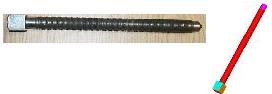
Preloading Bolt: This component creates a force on the holding arm when it is tightened against the shaft to remove the pulley from the shaft.
H-coreThis is basically a base on which the components of pulley puller are attached to perform the desired purpose.
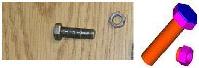
Nuts & boltThese are to attach the holding arm on to the H-core.
Working:
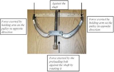
The Mechanism on which the pulley puller works is as follows.
The whole assembly of pulley puller is fixed to the pulley, which is to be removed from the shaft in such a way that the two holding arms are clawed to the pulley. Holding arm can rotate about the bolt axis to adjust the position of its jaws according to the diameter of the pulley. Then the other end of the preloading bolt is tightened against the shaft on which the pulley is mounted. This tightening of the preloading bolt against the shaft creates a force on the jaws of the holding arm in the opposite direction, which helps the holding arm to pull the pulley out of the shaft.
This is to demonstrate the force on the actual pulley puller to pull out the pulley from the shaft.
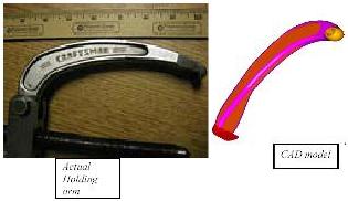
Holding Arm:
This is the main component of the pulley puller, which actually pulls the object like pulley from the shaft. One end of the holding arm has a hole so as to mount it on the H-core using a nut-bolt so as to provide it rotational degree of freedom in two directions other than the axis of the nut bolt plane in which it is attached. The other end of the holding arm has a wider cross-section and a curved jaw in the end so as to claw one end of the pulley and to remove the pulley out with the force created on it.
Procedure Used for Making the holding arm.
Х Rectangular Cross section of required dimensions were created at the required coordinates and were given the required orietation.
Х A circular crosection was made and revolved to form one end of the arm.
Х Points were created on the center of each side of rectangular crossections which are at an angle so as to join them with spline and using the thicken option to make the first half of the arm.
Х Loft was used to make the rest of the arm using other crosssections.
Х The last section was revolved by 180 degreees and was cut by a plane at 45degrees.
Х Recess in the part was drawn using splines and offsetting it and then making a cut of required depth.
Х Fillets were given on all the edges.
Difficulties.
Problem was in making the outer profile of the part so as to make the profile smooth for which only required points were joint using the spline leaving the other.
Recommendation for FE modeling
For Finite element modeling some of the features should be suppressed.These may include the fillets given on the outer edges of the part .Also fillet provided on the recess on both sides of the part should be suppressed.
H-CORE
This is basically a base on which the components of pulley puller are attached to perform the desired purpose.
Procedure Used for Making the H-core
Х Extrude command was used to make the desired shape with a I crossection and desired hole were created with cut command.
Х Surface was created on on side of the core using 3-D points and 3-D arcs and surface was created at a normal vector and were joint by loft command.
Х This part was used as a cutter part to make the desired shape at one corner and in the same way other corners were shaped using the reflect-cut command.
Х Other not required parts were cut using extrude command.
Difficulties.
Problem was in making the surface on the corner edges using the 3-d points and 3-D arcs.
Recommendation for FE modeling
For Finite element modeling some of the features should be suppressed.These may include the fillets given on the outer edges of the part .
PRE-LOADING BOLT
This component creates a force on the holding arm when it is tightened against the shaft to remove the pulley from the shaft.
Procedure Used for Making the Pre-loading bolt
Х Extrude command was used to make the top of the bolt with rectangular crossection
Х Skeching plane was moved on desired surface and again extrude command was used to make rest of the bolt.
Х The pin end of the bolt was made using the loft command
Х Desired fillets were given.
Recommendation for FE modeling
Х For Finite element modeling some of the features should be suppressed.These may include the fillets given on the outer edges of the part .
MISCELLANEOUS (NUTS AND BOLTS)Procedure:
Extrude command was used on the desired crosssection to make the parts.
FINAL ASSEMBLY
The final assembly consists of all the parts H-core, Holding arm (2), Nut & bolt (2), Preloading bolt in their respective position as in the actual pulley puller.
Procedure:
Х All the parts made were named and were kept in manage bins.
Х Then each part was taken out and was aligned using the align command depending upon its location.
Х Align command was used depending upon the part and the surface to which part are to be aligned.
Х Once the part was aligned the using the coincident and collinear command the axis of both the parts were constraint.
Х Similarly each part each part was taken out of bin and was aligned and then constrained.

MASS PROPERTIES
2-D Drawing
2-D drawing was created using the master-drafting task in design application. Corresponding part drawing was imported in the create drawing menu and after deciding about the types of views (standard views) and the scaling factor, different views were created after deciding on the view location. Then the required dimensioning was done using different options for the type of dimension. Following is the 2-D drawing of the Holding arm and H-Core with all four standard views.
2-D Drawing of H-core (units in mm)(*)
2-D Drawing of Holding arm (units in mm)(*)
CAD Modeling Practices
Pulley puller was made using the Master series. All the parts were made separately and were kept in the manage bin and were later recovered at the time of assembly. Assembly was done by using the align command and using the collinear and coincident constraint. Some difficulties were also faced in making the axis of the parts coincident in the wire frame view during the assembly.
MS could have been more helpful in assembling the components of the pulley puller by using the master assembly task.
MECHANICAL ANALYSIS SECTION
Holding Arm
To create the FEM model of the pulley puller, it was decided to model one of the holding arms using shells and the other one using the beams.
Using Shell
To create the shell model of the holding arm, a surface was created at the parallel cross section, which passes through the center of the holding arm. This surface was created using a extrude command with a partition. This surface was extracted and was then used to create shell mesh on it. Free mesh was used with a element length of 5 and thickness of the elements as 11.before creating the shell mesh an anchor node was created at the center of the hole in the arm.
Beam Model
Beam model was created using the cross sections of the holding arm at different locations along the length. Cross sections were created using the extrude command with partition. These sections were extracted and then stored. Nodes were created along the centerline passing through the arm at appropriate distances. These nodes were then connected through the stored cross sections at that location.
This beam model of the holding arm acts like a two force member as the force acting along the arm will act along the line connecting the first and last node on the arm.
As a force of 5000 lbs is applied in the z direction the holding arm will have stresses both tensile and compressive. As the stresses are developed in holding arm, it will be compressive on the inner side and tensile on the outer side. As seen in one of the homework, the stress was highest in the arm where the beam section was the farthest from the line of action of the 2-force member. Also a maximum displacement of 3.57 E+04 was seen when a force of 1000 lbs was applied. Using these results we could predict that the final FE model will also develop high stresses in the same region of the arm and will definitely transfer the load to the h-core to cause its displacement.(*)
H-Core
H-core was modeled using the linear tetragon elements. Before modeling the h-core, fillets on the h-core were suppressed. Linear tetras were used in the H-core to minimize the solution time. Though linear tetras are stiff elements, since the H-core is a rigid component the final solution will not be affected as h-core itself is considered to be a rigid component.(*)
Preloaded bolt
Preloaded bolt was modeled using the beam elements. Beam section was created using the extrude command with a partition. This section was then extracted and was used to create beam model of the bolt. This beam model of the bolt was connected to the H-core through a node which itself is connected to the other nodes of the h-core via spider elements. Using the spider elements to connect the bolt to the H-core makes the bolt completely constraint and can be assumed to a welded joint.(*)
Bolted Connections
In order to connect the holding arm with the h-core beams were used. Two beams were created between the outer nodes of the hole on the h-core and a center node (20007). These outer nodes are the constraint node and connected with spider elements. This will allow complete transfer of load between preload bolt and the h-core.(*)
Connections
In order to connect the holding arm (one with shell elements and the other with beams) center node of the beam (bolt) and anchor node of the arm was aligned after deciding the coincident nodes. These nodes were the connected with a translational and a rotational spring with a high stiffness of the order of 1 E+10.The translation spring was connected giving the restraint for degree of freedom in x, y, z . Rotational spring was restraint for given dof in Rx and Ry. This will allow rotation about the Z-axis free.
Final FE Assembly
For the final assembly of the FEM model of the pulley puller, finite element model of all the components are connected. In ideas9 at a time one FE model can be on screen for which APPEND command was used to attach the FE model of the holding arm to the FE model of the h-core and same way was followed to append the other FE model of arm to connect them. Beam model was created for the bolt using the spider elements on the h-core and the holding arm was attached to the beam model of bolt with spring elements. To analyze the assembly, a load of 5000lbs was applied to preloaded bolt in +Y direction.The two bottom ends of the holding arm was restraint in DOF 1,2,3,4,5 and the top end of the preloaded bolt was restraint in DOF 1,3,4,5,6.This restraint was applied in order to not have any asymmetric deflection in the assembly as different model are used to model the two holding arm, which can result in asymmetry. The arm is supported at an angle of 30 degrees assuming the position of arm while pulling out the pulley from the shaft.(*)
FE Mass Properties(*)
Comparing the mass of the cad model with the FE model
Mass of CAD model = 1.2328 kg Mass of FE model = 1.186 kg
Difference = 1.2328-1.186 = 0.0468 kg
The difference in the mass and the location of the center of gravity is due to the reason
that shell mesh is bean used for one of the holding arms.
Loads and Restraints
From the FBD we can see restraint are applied at point A and B on the holding arm killing degrees of freedom in 1,2,3,4,5 so that it can only rotate about the Z.A vertical force of 5000 lbs is applied at Point C. In order to transfer load between the bolt and the arm spring elements are used (both translational and rotational with high stiffness) Even after all these restraints the assembly contains a 3-link mechanism which means it will give a singular matrix, that means that the h-core can also rotate about Z direction, which will result in asymmetric deflection of the assembly. In order to restrict this type of deflection the top node D is restraint so that the h-core will not rotate but can have displacement in Y direction. If the model is fully symmetric then the reaction force at this node will be Zero.
Results-Deflected Shape
I-DEAS 9 : Simulation 06-Dec-02 11:52:20
/home3/classes/sp02/egn5858/ps/fp.mf1
Group ID : None
Result Set : 1 - B.C. 1,DISPLACEMENT_1,LOAD SET 1
Report Type : Contour Units : MM
Result Type : DISPLACEMENT
Frame of Reference: Part Data Component: Magnitude
Node Displa-X Displa-Y Displa-Z Displa-RX Displa-RY Displa-RZ
20647 0.000E+00 0.000E+00 0.000E+00 0.000E+00 0.000E+00 -2.204E-02
20809 0.000E+00 1.332E+00 -1.486E-04 -6.558E-06 -1.369E-05 8.382E-04
20794 0.000E+00 0.000E+00 0.000E+00 0.000E+00 0.000E+00 1.464E-02
From the plot of the deflected shape and also from the report output we can see the
maximum displacement is 1.49mm in + y direction and the other nodes A and B has no
displacement in x and y directions as defined from the constraints.
From this the model appears to be completely symmetric as node D has no displacement
in X but has some in Y direction so some asymmetry is definitely there.
From homework problem, where one of the arms was modeled using the beams,
displacement was noted so it could have been predicted here also that there will be some
displacement for the h-core.
Results ЦStresses
I-DEAS 9 : Simulation 06-Dec-02 11:57:39
/home3/classes/sp02/egn5858/ps/fp.mf1
Group ID : None
Result Set : 3 - B.C. 1,STRESS_3,LOAD SET 1
Report Type : Contour Units : MM
Result Type : STRESS
Frame of Reference: Part Data Component: Von Mises
Surface Type : Top
Max Prin Mid Prin Min Prin Max Shear Von Mises 20607 20079 20761 20607 20607 Maximum 7.523E+05 4.204E+04 3.661E+04 3.761E+05 7.452E+05
20093 20089 20570 20544 20544 Minimum -2.753E+04 -1.159E+05 -5.640E+05 1.838E+03 3.367E+03
Average 6.668E+04 -2.724E+03 -4.966E+04 5.896E+04 1.120E+05
Above is the combined stress plot for both shell and beam model stresses. As seen from the homework problem, stresses are maximum at the center location of the arm in the beam model so stresses in this case will also be higher, since we are using shell elements in the other arm stresses in this will be higher than the beam model as shell elements are more stiff than beam and also the stresses in the shell elements will be higher at the center location of the arm and on the inner side of the holding arm.
Results ЦRestraint Forces
I-DEAS 9 : Simulation 06-Dec-02 11:49:02
/home3/classes/sp02/egn5858/ps/fp.mf1
Group ID : None
Result Set : 2 - B.C. 1,REACTION FORCE_2,LOAD SET 1
Report Type : Contour Units : MM
Result Type : REACTION FORCE
Frame of Reference : Part Data Component: Magnitude
Node Reacti-X Reacti-Y Reacti-Z Reacti-RX Reacti-RY Reacti-RZ
20647 -6.377E+06 -1.097E+07 6.713E+01 1.049E+04 1.808E+04 0.000E+00 20794 6.448E+06 -1.127E+07 -6.713E+01 -1.044E+04 -3.207E+04 0.000E+00
20809 -7.076E+04 0.000E+00 0.000E+00 0.000E+00 0.000E+00 0.000E+00
Total -1.641E-01 -2.224E+07 -7.629E-06 5.068E+01 -1.398E+04 0.000E+00
20794 20809 20647 20647 20647 20647 Maximum 6.448E+06 0.000E+00 6.713E+01 1.049E+04 1.808E+04 0.000E+00
20647 20794 20794 20794 20794 20647 Minimum -6.377E+06 -1.127E+07 -6.713E+01 -1.044E+04 -3.207E+04 0.000E+00
Average -5.469E-02 -7.414E+06 -2.543E-06 1.689E+01 -4.661E+03 0.000E+00
From the free body diagram
RAsin30 Ц RBsin30 + RD = 0 ЕЕЕЕЕЕ..(1)
RAcos30 + RBcos30 + 5000(lbs) = 0ЕЕЕЕЕЕЕ.(2)
From the out put :
RAsin30 = 6.448E+06 N
RBsin30 = -6.377E+06 N
RAcos30 = -1.4097E+074 N
RBcos30 = 1.127E+07 N
Substituting these values in eq(1) and eq(2) we get RD = -7.076E+04 N
Which is the same as we get from the plot.
If the assembly was fully symmetric then this force developed should have been Zero, since we have modeled the two holding arm with different types of elements, we got this reaction at node D which shows a asymmetric model.
CONCLUSIONS/RECOMMENDATIONS
For FEM analysis of the pulley puller, various assumptions were taken to model different parts of the puller. Since h-core and the holding arm had fillets etc, these features were suppressed to make the analysis simple.
In order to analyze the puller, one of the arms was modeled using shells and one with the beams. This could have induced some asymmetry in the model, which was later proved in the analysis. Since different FE model were connected we made use of the spider elements, in order to properly transmit the required degrees of freedom.
Finally to analyze the model loads and restraints were given to look for the displacement, stress, and reaction forces.
Also in order to prevent the 3-bar mechanism, restrain was also introduced. Append command was also used to put all the FE models together.
Master series was used to make the 3-D model of the pulley puller. All the parts were made separately and were kept in the manage bin and were later recovered at the time of assembly. There was some difficulty in adding features on the h-core and the holding arm. Assembly was done by using the align command and using the collinear and coincident constraint. Some difficulties were also faced in making the axis of the parts coincident in the wire frame view during the assembly.
MS could have been more helpful in assembling the components of the pulley puller by using the master assembly task.
MS was good in analyzing the results as we got what we had predicted from the loading condition, the maximum displacement was 1.49mm.
Also the results for the stress were as predicted for the beams and the shells.
Results for the reaction forces also matched with one we got from the FBD of the model.
APPENDIX
Attached herewith:
ƒонЌ“”>
ѕортал магистров ƒонЌ“”>
јвтореферат |Ѕиблиотека |
—сылки |
ќтчет о поиске | »ндивидуальное задание