 alialkaissi@yahoo.com
ALI JAMAL JASSIM
Faculty: Electrotechnical
Speciality: Electrical systems and networks
Leader of work: proff.ass. Dmitry Polkovnichenko
Theme of master's work:
RESEARCH OF OPPORTUNITIES OF TRANSITION FROM SYSTEM OF PRECAUTIONARY REPAIRS TO SYSTEM OF SERVICE ASYNCHRONOUS ELECTRIC MOTORS WITHOUT RECTIFYER AND ON THE CONDITION
Materials on the theme of master's work: Biography \ Links \ Report about the search.
Introduction
Now asynchronous engines are the most widespread electric machines. They consume about 40 % of the electric power made in the world. Asynchronous electric motors have received such extensive distribution because of the constructive simplicity, low cost, high operational reliability.
Alongside with greater advantages asynchronous engines have also some lacks - damages of elements of the engine are while in service possible, that in turn leads to his premature output exit out of operation.
Principal causes of failure of engines of an alternating current are: damages of elements stator and a rotor, bearings and another. It leads to infringement of a continuity of technological processes with the subsequent marriage of production, expenses for restoration and repair of electric motors, and also for restoration of normal technological processes of manufacture. Process of automation of management by technological processes by use of diagnosing of a technical condition of electric motors in an operating conditions allows to lower to a minimum damage from these consequences due to early detection of defects.
Urgency of a theme
Operation of electric motors being an emergency technical condition leads to the direct financial losses connected with not predicted failure of the equipment and caused by this infringement of technological process, and to the significant additional expenses of the electric power caused by the increased power consumption. In this connection the question of diagnostics of asynchronous engines is rather actual.
Process of automation of management by technological processes by use of diagnosing of a technical condition of the equipment including electric motors, in an operating conditions allows to lower to a minimum damage from these consequences due to early detection of defects. The control and the analysis of a current technical condition allow to introduce technology of service of electric motors « on a condition ». That is service and repair are carried out depending on a real current technical condition of the electric motor which is in work.
Thus, the problem of development and perfection of methods and means of diagnosing of a technical condition of electric motors on the basis of the control of parameters of an operating conditions is actual.
The purpose of work.
To research opportunities of transition from system of precautionary repairs to system mishear asynchronous electric motors and technology of service and repair depending on a technical condition of the electric motor, that is « on a condition ».
Scientific novelty of work
In spite of the fact that asynchronous engines are very simple in application, at the enterprises not enough time is given for diagnosing and between-repairs service to what frequent damageability of these engines testifies. Considering it, it is necessary to develop such methods which would allow to diagnose a condition of engines in an operating conditions and would not suppose failures and large repairs. Such method is already developed is a method « on a condition », therefore in work we wish to bring to a focus to him and to try to make the most exact calculations.
Practical value of work
The method will be developed for detection of the broken edges in powerful engines which is based on the control of density of a magnetic stream over edges of a rotor (usually they a little support flit a rotor in these engines).
The maintenance of work.
One of methods of research is the diagnosis broken bar in greater engines of an induction excitement of a stream of outflow. There is an opportunity to find out presence of the broken edges, researching a spectrum of a current stator. The broken edge leads to that components of a current which is induced on a winding stator at frequencies:
Where:
fsb = minor frequencies because of the broken edges of a rotor, Hz
f1 = nominal frequency, Hz
s=в Sliding
In more detail see a method based on the control of density of a magnetic stream about edges.
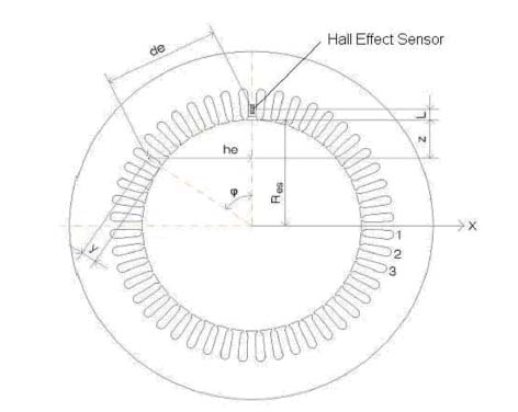
The density of a magnetic current in the gauge holl is calculated, applying law Biot Savart ' s for each edge, and for currents stator. The Fig. 1 shows the modelling, the offered method.
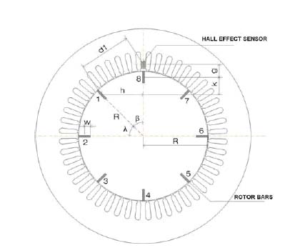
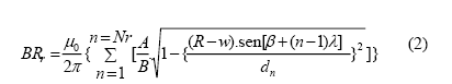
The rotor contribution for the resulting magnetic flux density in the sensor is given by:
Where:
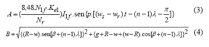
A = current flowing in each the rotor bar
dn = distance between sensor and a bar center
BRr = resulting magnetic flux density by rotor currents
R= rotor radius
G=minimum distance between sensor and a bar center For the stator contribution, the Biot Savart 's law was applied in each stator slot, as shown by eq. (8).
Where:
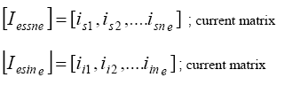
Eq.(6) shows the distance matrix between stator slots and sensor axis.
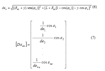
Fig. 2 shows the structure used in the modelling of stator currents.
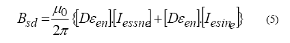
The resulting magnetic flux density in the Hall effect sensor by rotor and stator currents is given by eq. (8):
![]()
Where:
BT = resulting magnetic flux density on sensor
The mathematical model based in (8) was implemented in the MATLAB/SIMULINK software. The model was simulated for a healthy and faulted rotor. For simulation purposes the parameters where used as shown in the Table 1, from a hypothetical induction motor. In fig. 3 it is possible to observe the resulting magnetic field density on a Hall effect sensor, obtained for a healthy motor, without broken rotor bars. In Fig. 4 it's shown a simulation with two broken rotor bars. During simulation has been noticed a resulting magnetic field density variation, mainly when the broken bars were near the sensor. For a fault simulation, the broken bar current is set to zero in the MATLAB model.
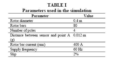
Tab.1
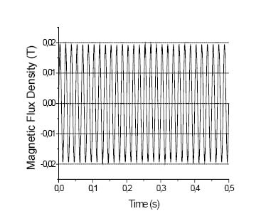
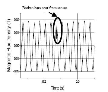
Fig.3 Fig.4
Experimental tests were made in order to validate the mathematical modelling. Fig. 5 shows the installation of the Hall effect sensor between two stator coils in an induction motor. Its rotor is composed by 58 bars. In Fig. 6, it is possible to observe the initial experimental results obtained for a faulted rotor with two broken bars. In this case, it was noticed that the resulting magnetic field density in the sensor has the similar behavior with the simulation results. Broken bars near from sensor Fig. 6 shows a good approach between simulation and experimental results. In this case, it was considered the stator contribution, applying Biot Savart Law for each stator slot current. In Fig. 7 it is possible to observe the magnetic flux density variation in the hall effect sensor in more details, in the negative cicle. Fig. 8 and fig. 9 show the bar current distribution.
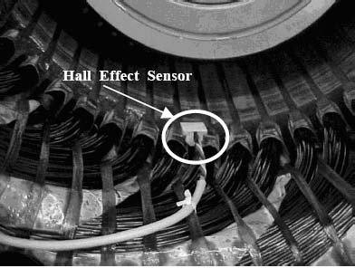
Fig.5
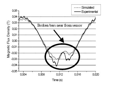
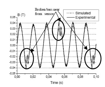
Fig.6 Fig.7
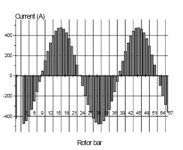
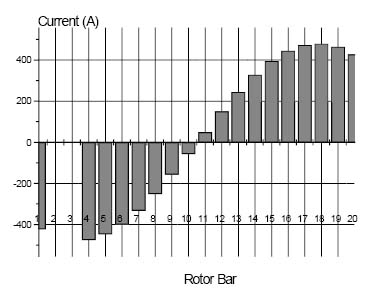
Fig.8 Fig.9
Fig. 10 shows the magnetic flux density variation in a positive cycle. Fig 11 show the bar current distribution for a positive cycle.
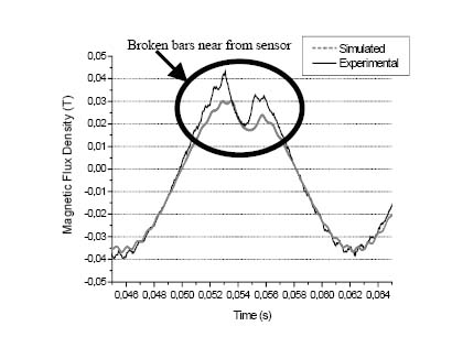
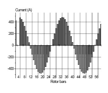
Fig. 10 Fig.11
We considered one of methods of research is diagnosis of the broken bars in the large engines of induction by agitation of stream of loss. It is desirable to mark that developments of the automatic and automated systems of diagnostics of electric motors appeared with development of the computing engineering (for example, on рис.12). Thus for their realization as diagnostic parameters different operating parameters of electric motor are offered.
Fig.12
CONCLUSIONS ON WORK
Research of behaviour of the engine of an induction became fundamental because it is necessary to avoid losses of manufacture which are applied in the industry. Three-phase engines with the squirrel cage are widely used on manufacture. Now, it is very important to know operational conditions of the engine in a mode of real time, to reduce unforeseen breakages, an idle time and operational expenses. During work of the engine, many breakages it is possible to avoid, considering electric and mechanical breakages.
So, one of methods of research is the quality monitoring and density of a magnetic stream about edges of a rotor. We have made calculations and were convinced of necessity of the given method.
THE LITERATURE
1. C. Kral, F. Pirker, G. Pascoli, H. Oberguggenberger, Influence of rotor cage design on rotor fault detection by means of the Vienna Monitoring Method. International conference on electrical machines (ICEM-2002), Old St. Jan Conference Center, Brugge, Belgium, Conference Record.
2. C. Kral, F. Pirker, Vienna monitoring method – detection of faulty rotor bars by means of a portable measurement system. International conference on electrical machines (ICEM-2000), Helsenki University of technology, Espoo, Finland, p.873-877.
3. Williamson S, Smith A.C.: "Steady-state analysis of 3-phase cage motors with rotor-bar and end-ring faults", IEE Proceedings, Vol. 129, Pt. B, No. 3, pp 93-100, May 1982.
4. Siyambalapitiya D.J.T, McLaren P.G, Acarnley P.P.: "A Rotor Condition Monitor for Squirrel-Cage Induction Machines", IEEE Transactions on Industry Applications, Vol. IA-23, No. 2, pp 334-340, March/April 1987.
5. Kliman G.B, Koegl R.A.: "NonInvasive Detection of Broken Rotor Bar in Operating Induction Motors", IEEE Transactions on Energy Conversion, Vol. 3, No. 4, pp 873-879, December 1988.
6. Thomson, W.T.: "On Line Current Monitoring The Influence on Mechanical Load or an Unique Design on the Diagnosis of Broken Bars in Induction Motors", Proceedings of the International Conference on Electrical Machines, Manchester (UK), Vol.3, pp 1236-1240, 1992
7. Cho, K.R, Lang J.H, Umans S.D.:" Detection of Broken Rotor Bars in Induction Motors Using State and Parameter Estimation", IEEE Transactions on Industry Applications, Vol. 28, No 3, pp 702-709, May/June 1992.
8. Walliser R.F, Landy C.F.: "The Influence of Interbar Currents on the Detection of Broken Rotor Bars" Proceedings of the International Conference on Electrical Machines, Manchester (UK), Vol.3, pp 1246-1250, 1992
9.Toliyat H.A, Lipo T.A.: "Transient Analysis of Cage Induction Machines Under Stator, Rotor Bar and End Ring Faults", IEEE Transactions on Energy Conversion, Vol.10, No.2, pp 241-247, June 1995. 1234567891011121314151617181920-400-2000200400Rotor BarsCurrent (A)
10. Luo X, Liao Y, Toliyat H.A, Antably A.E, Lipo T.A.: "Multiple Coupled Circuit Modeling of Induction Machines", IEEE Transactions on Industry Applications, Vol.31, No. 2, pp 311-318, March/April 1995.
11. Penman, J, Stavrou, A.: "Broken rotor bars: their effect on the transient performance of induction machines" IEE Proc.-Electr. Power Applications, Vol. 143, No. 6, pp 449 - 457, November 1996.
12. Fiser R, Ferkolj S.: "Modelling of Failure States of Induction Machines", Proceedings of the IEEE Mediterranean Electrotechnical Conference, Bari (Italy), Vol. 3, pp 1195-1198, 1996
13. Manolas S.T, Tegopoulos J, Papadopoulos M.: " Analysis of Squirrel Cage Induction Motors With Broken Rotor Bars", Proceedings of the International Conference on Electrical Machines, pp 19-23, 1996.
14. Fiser R, Ferkolj S.: "Calculation of Magnetic Field Asymmetry of Induction Motor with Rotor Faults", Proceedings of the IEEE Mediterranean Electrotechnical Conference, Tel Aviv (Israel), Vol.2, pp 1175-1179, 1998 Figure 13. Bar current distribution (in details for positive cycle)
25. Thomson W.T, Rankin D, Dorrell D.G.: "On-Line Current Monitoring to Diagnose Airgap Eccentricity in Large Three-phase Induction Motors - Industrial Case Histories Verify the Predictions" IEEE

