Rotor Fault Analysis of a Permanent Magnet Synchronous Machine
W. le Roux, R.G. Harley and T.G. Habetler
School for Electrical and Computer Engineering,
Georgia Institute of Technology
Atlanta, Georgia, 30332, USA
Phone: +1 404 894 9829, e-mail: thabetler@ee.gatech.edu
Приведеная статья была одним из докладов на 15-ой международной конференции по электрическим машинам "ICEM - 2002". Список статей которые докладывались на конференции, среди которых находится и данная статья находятся по адресу: http://icem.metu.edu.tr/icem2002content.htm
Abstract — In this paper, the detection of rotor faults in converter fed permanent magnet synchronous machines is investigated. Various faults, such as static eccentricity, dynamic eccentricity, and flux disturbances, are introduced by finite element simulation to obtain winding inductances and rotor flux linkages as a function of rotor position. These parameters are used in a transient simulation of the faulted machine to extract the harmonic content of the stator current. A method is developed to detect these faults and distinguish between them based on the harmonic content. Experimental measurements are shown to support the simulation.
1. Introduction
The high power density and high efficiency of the permanent magnet (PM) machine has led to the use of this machine in applications in which the high reliability of the machine is a key feature, such as aerospace/aircraft actuators, automotive auxiliaries, and hostile environments as in mines and/or nuclear plants. The switched reluctance motor drive has also been developed for these applications because of its inherent fault tolerance [1]. However, the switched reluctance machine has a lower power density compared to the PM machine. If PM drives are to be considered for these applications, they have to be designed to be very reliable. Redundancy and conservative design techniques have been widely adopted for improving the reliability of these drives against the variety of faults that can occur [2]. As an alternative to these expensive techniques, considerable diagnostic strategies and control schemes can be devised to ensure a fault tolerant drive.
The work reported in this paper relates to permanent magnet synchronous machines (PMSM), specifically regarding rotor faults. With PMSM, other authors have done work to detect turn-to-turn and loss of phase faults of the stator windings [1][3] and to detect open and short circuit failures of the drive connected to the PMSM [4][5][6]. Much work remains to be done on detecting rotor and bearing faults in PMSM. This paper focuses on detecting three categories of rotor faults, namely static eccentricity, dynamic eccentricity, and flux disturbances originating from defects to the permanent magnets.
Load unbalance, misalignment, improper mounting, and a bent rotor shaft can all cause rotor eccentricities. These eccentricities can be divided into static and dynamic eccentricities. Static eccentricity is when the rotor is shifted from its normal position at the center of the stator and it rotates in that position. With dynamic eccentricity, the rotor is also shifted from the normal position, but now rotates around the center of the stator.
Another rotor fault that can occur is an air-gap flux disturbance due to some defect to the permanent magnets.
It is known that some permanent magnets (Nd-Fe-B) corrode, which leads to disintegration [7]. Cracks that form during manufacturing can also lead to disintegration at high speed [8]. Furthermore, demagnetization of the magnets [9] can cause flux disturbances.
These rotor faults cause problems such as vibration and noise due to unbalanced magnetic pull (UMP). It also causes dynamic problems by adding to torque pulsations.
In the literature, PM machines (with eccentricity faults) are modeled either by modulating the air-gap (varying permeance method) in one dimension [10][11] [12] or two dimensions [13], or the governing field equations and associated boundary conditions are formulated and solved by a perturbation method as in [14]. These methods are usually checked by finite element methods (FEM).
In this paper, the rotor faults are implemented by FEM simulation. Simulation of the motor equations yields steady-state stator quantities that are investigated for use in detecting these faults. This is followed by a comparison with results from an experimental setup.
2. FEM Fault Implementation
A 2 kW PMSM, 4-pole machine with surface mounted permanent magnets was designed in ANSOFT® software. The 2D model of the machine appears in Fig. 1.

Fig.1. 2D Model of PMSM.
The machine has 36 slots and a double-layer three-phase winding. The windings are short-pitched by one slot. With no current flowing in the windings, the magnetic fields are solved by finite element software for a specific rotor position. This yields the permanent magnet flux linking the stator windings and the winding inductances. The rotor is then rotated by a pre-specified angle (0.36o) and the flux linkages and inductances are re-calculated. This process is repeated until the rotor is rotated through a full revolution. This process gives flux linkages and inductances as a function of rotor position, which can be used later in a look-up table in a transient simulation of the motor. The magnet flux linking the a-phase winding and the a-phase inductance is shown in Fig.2 for one rotor revolution.

Fig.2. Magnet flux linking a-phase and a-phase inductance.
This procedure is first followed to yield the quantities of Fig.2 for the normal motor. In Fig.2, the magnet flux linking the stator varies sinusoidal through two periods for one rotation, since this is a 4-pole machine. Also, even in the normal machine, the flux waveform contains other harmonics due to the non-ideal non-sinusoidal winding function. For the same reason and because of stator teeth, the inductance waveform in Fig.2 is not DC (the inductance changes with rotor position), but contains harmonics.
This process is repeated for the various rotor faults:
- Static eccentricity: the rotor is displaced from the center of the stator by 32% in the 2D modeler. The rotor is then rotated around its own center.
- Dynamic eccentricity: the rotor is again displaced, but now rotates around the center of the stator.
- Flux disturbance: the rotor rotates in its normal position, but one of the magnets is made 22% smaller, simulating a missing magnet piece along the axial rotor length.
3. MATLAB Simulation
The PMSM drive shown in Fig.3 is simulated in MATLAB®, solving for the motor differential equations and mechanical load equation by numerical integration in a transient simulation. From the rotor position, speed, and the two look-up tables discussed in the previous section, the back-emf of the machine is calculated for any instant in time. The system in Fig.3 is a typical PMSM drive with speed reference, pulse width modulated PWM voltage source inverter (VSI), speed and position feedback, and current controllers in the rotor rotating reference frame.
The drive is simulated during an increase in motor speed from standstill to a set-speed. After steady state is reached, stator currents and voltages are sampled. This process is done for the normal motor as well as for the various rotor fault conditions. The control loops are also implemented in the software. The PMSM is simulated in the qd-reference frame, since the current controllers operate in this reference frame. Another advantage is that this yields an easy method to ensure no zero sequence currents are flowing for a three-wire case.
Using conventional field orientation, the well-known decoupled equations in the rotor reference frame with ids set to zero are given by
![]()
where Lqs is the q-axis stator inductance, ωr is the rotor speed in electrical radians per seconds, λd ( pm) is the d-axis magnet flux linkage, and p is the differentiation operator.
Because of the variations in the magnet flux linkage and the stator inductance (due to the harmonics mentioned in the previous section), (1) must be rewritten as in (2), where Ls is the stator winding inductance matrix and T is the rotor reference frame transformation matrix.

Lqd 0 is given in (3).
![]()
The differential equations that need to be solved are thus as given in (4). With no neutral wire only ids and iqs are used in the numerical integration, with i0s always set to zero). Since the magnet flux and stator inductances contain harmonics, the stator voltages and currents will also contain these harmonics.

Fig.3. Flow diagram of PMSM drive system

4. Simulation Results
A. Investigating the Current Harmonics
As already mentioned, the magnet flux linkage and stator winding inductance contain harmonics even for the normal motor. If the sinusoidal variation of the magnet flux linkage in Fig.1 is taken as the fundamental, the prominent harmonics of the flux linkage in this simulated motor are 1 and 3, and the prominent harmonics of the inductance are 2, 4, and 6. The stator current thus contains harmonics at 1, 3, 5, 7, etc, with the exception of zero-sequence currents for a three-wire system. For different rotor faults, not only will the magnitude of these harmonic current components vary, but also new harmonic components will appear.
In the dynamic eccentricity case, the flux linkage and inductances have frequency components with a 0.5 harmonic number, and integer multiples thereof. This happens since one stator electrical fundamental period produce only half a rotation for a 4-pole machine. Because the position of minimum air-gap rotates with the rotor in this case, the flux linkage and winding inductance will be different in one half of the rotation compared to the other half of rotation. This produces harmonic components at the rotating frequency (harmonic number of 0.5). Thus, the position of the harmonic component to be monitored is 2 / P , where P is the number of poles.
In the static eccentricity case, these new harmonic components at the rotating frequency and multiples thereof are not encountered in the flux linkage and winding inductances. This is expected since the position of minimum air-gap is static in relation to the stator. However, there are differences in inductances between the phases. This phenomenon manifests itself in negative sequence components of the harmonic components that are already present in the normal machine.
In the flux disturbance case, the inductances do not contain any new spectral content at the rotating frequency. This is true since the relative permeability of the magnets is almost equal to one. Thus, the windings do not experience a larger air-gap for a missing magnet piece. However, due to the missing magnet piece, there is a step change in the flux density curve around the rotor. This results in a frequency component at the rotating frequency; i.e., at the harmonic number 0.5 and at multiples thereof.
At first, only the harmonic components of the d-axis current in the rotor rotating reference frame were considered. This was done since the current controllers are implemented in this reference frame and the d-axis current does not contain the current mostly responsible for generating torque. Therefore, it is easy to measure these frequency components and, in the rotor reference frame, the currents contain some information regarding phase sequence. For every positive sequence current component of harmonic number h , in the abc-reference frame, the harmonic number of this component in the rotor rotating reference frame will be h -1 due to the transformation. If this component is of negative sequence, the harmonic number in the qd-frame will be h +1. Thus, the current harmonic components in the qd-frame that are monitored are the following: 2, 4, 6, etc. (components that are present in the normal motor) and 0.5, 1, 1.5, 2.5, 3, etc. (new components due to rotating fault).
A summary of the MATLAB simulation of the rotor faults is given in Table I. The table shows the harmonic components in the d-axis current at different harmonics. The amplitude at each harmonic is normalized to the amplitude of the same harmonic in the normal motor case. As can be seen, different combinations of harmonics increase for different faults.
Table 1 – Normalized harmonic amplitudes of d-axis current
Harmonic number |
Normal rotor |
Dynamic eccentricity |
Flux disturbance |
Static eccentr. |
2 |
1.0 |
0.6 |
0.4 |
0.5 |
4 |
1.0 |
2.4 |
4.4 |
4.9 |
6 |
1.0 |
1.1 |
1.4 |
1.0 |
0.5 |
1.0 |
8.5 |
5.0 |
1.0 |
1 |
1.0 |
7.7 |
2.5 |
1.0 |
1.5 |
1.0 |
5.0 |
2.7 |
1.0 |
2.5 |
1.0 |
4.0 |
4.6 |
1.0 |
3 |
1.0 |
7.5 |
0.9 |
1.0 |
As previously explained, the dynamic eccentricity and flux disturbance faults can easily be detected by the increase in harmonic component at the rotating frequency (in this case harmonic 0.5) and integer multiples of this frequency. These components do not increase for the static eccentricity case. Also, for the already prominent frequency components in the normal motor (harmonics 2, 4, and 6 in Table I), the amplitudes are different for the different faults.
In Fig.4, an FFT is shown of the total current in the rotor reference frame. The top graph clearly shows the components at the rotating speed harmonic (0.5).

Fig.4. FFT of qd-current. Dynamic eccentricity: solid line; Flux disturbance: dotted line; Static eccentricity: dashed line, Normal motor: dotted-dashed line. Speed : 1900 rpm.
The bottom graph zooms into the 0.5 harmonic components, showing that this harmonic component only shows up for the dynamic eccentricity and flux disturbance cases.
B. Observations
Examining the amplitudes of the harmonics in the rotor frame as done in the previous section might be misleading, since different faults are compared with each other. The severity of the fault may cause changes in the values given in Table I.
Another misleading factor is the reference frame. One of the reasons the qd-frame is used is that it contains sequence information. For example, assume the self inductance contains harmonics that result in a balanced fifth harmonic three-phase current in the abc-reference frame. The fifth harmonic is a negative sequence harmonic, and this current component will transform to a sixth harmonic in the qd-reference frame. In the static eccentricity case, the different inductances between the phases will cause an unbalanced fifth harmonic current in the abc-frame. Thus, there is a positive sequence component at the fifth harmonic which transforms to a fourth harmonic in the qd-frame. However, other harmonic components could also get transformed to the same harmonic position in the qd-frame, thus making it impossible to distinguish the source of the spectral components.
Also, the advantage of not having the torque producing current in the d-axis current, thus making it easier to detect these harmonics without filtering, is not quite correct. The d-axis current is not something that is measured at the terminals of the machine, but exists in the control loops of the microprocessor. Even there the accuracy is a function of the number of bits in the analogue-to-digital converter.
This method is also significantly influenced by the type and construction of the motor. For example, for this simulated motor and from Table I, the third harmonic could be used to distinguish between a dynamic eccentricity and a flux disturbance fault. However, for other motors with different winding arrangements and abnormalities, this harmonic number might not be used. This is illustrated by experimental results on a different motor shown in the next section. It is thus necessary to investigate each motor on its own and establish baseline amplitudes for the current harmonic components through measurements of the normal motor under different operating conditions.
C. Investigating Harmonic Components in abc-frame
Since monitoring the harmonic components in the rotor reference frame can obscure the fault effects, the harmonic components of the current in the abc-reference frame are also investigated for sequence information.
The prominent stator current harmonics are 5 and 7. Both are transformed to the sixth harmonic position in the rotor reference frame. In a normal motor, the three-phase fifth and seven harmonics are balanced, the fifth harmonic being of negative sequence and the seventh of positive sequence. For the dynamic eccentricity, these harmonic components increase due to the rotating fault, but they are still balanced. In the static eccentricity case, the fifth harmonic exhibits a positive sequence component while the seventh harmonic in turn contains a negative sequence component. This is due to the unbalance between phases caused by the static eccentricity. Table II shows the sequence components for the seventh harmonic in the abc-reference frame. It is clear that the negative sequence component increases for the static eccentricity.
Table 2. – Sequence components of the seventh harmonic current in the abc-reference frame (given in milli-amperes)
Sequence of 7th Harmonic |
Normal rotor |
Dynamic eccentricity |
Flux disturbance |
Static eccentr. |
Positive |
2.6 |
3.6 |
2.1 |
3.2 |
Negative |
0.3 |
0.3 |
0.3 |
0.9 |
4. Experimental Results
Experiments were done on a 2.85 kW, 4-pole, surface mounted permanent magnet synchronous machine. A 4 kW inverter feeds the motor with the current controllers in the rotor reference frame and with rotor position feedback from a shaft resolver. A DC dynamometer was used to load the motor. The various rotor faults discussed in this paper were simulated by different methods.
A. Dynamic Eccentricity
Various authors have simulated dynamic eccentricity by mounting an unbalanced disc on the shaft of the motor under test [10]. Dynamic eccentricity can be caused by misalignment of bearings, mechanical resonance at critical speeds, a bent rotor shaft, or bearing wear. The unbalanced disc creates a vibration and rotor movement mainly at the rotating speed. It also adds a position-dependent load torque.

Fig.5. FFT of qd-current with unbalanced disc (speed 1800 rpm).
Fig.5 shows the Fourier components of the qd-current for the unbalanced disc case. The current component at the 0.5 harmonic is clearly visible. Fig.6 shows an increase in this harmonic component with an increase in unbalance, where each bar in Fig.6 represents a test result with increased unbalance from the left. This harmonic component with an increase in unbalance, where each bar in Fig.6 represents a test result with increased unbalance from the left.
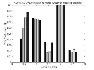
Fig.6. Progression of unbalance.
B. Static Eccentricity
To simulate static eccentricity, the stator housing is machined larger at the position of the bearings. Shims are then inserted into the machined space to offset the rotor from its normal center position. This is shown in Fig.7. The rotor then rotates in this new position, which is a true static eccentricity according to the definition. This can only be done at one end of the machine, since there is a shaft resolver installed at the other end with a very small air-gap.

Fig.7. Implementation of static eccentricity.
The stator was moved by 20% at one end of the motor. The results are shown in Fig.8.
In Fig.8, the first few harmonic components are shown for the static eccentricity case and for the motor without eccentricity. The harmonics 1, 2, 3, and 4 are all present in both cases and there is not much difference between the amplitudes of these components when the eccentricity case is compared with the normal case. These harmonics are present because of the non-ideal winding distribution as explained earlier. Note that these harmonics and amplitudes are different than for the motor that was simulated in the previous section. It can be seen that there is no component at the rotating frequency harmonic (0.5) or at 1.5, 2.5, etc. The bottom graph of Fig.8 is a zoom into the 0.5 harmonic components to show that the static eccentricity does not increase the harmonic component at 0.5. Also, there are noticeable differences between the two test results when comparing positive and negative sequence currents of a specific harmonic. For example, for the fifth harmonic, the positive sequence component changes when the static eccentricity is introduced.

Fig.8. Implementation of static eccentricity (speed 400 rpm).
Static eccentricity case: solid line; without eccentricity: dashed.
C. Flux Disturbance
For a flux disturbance, a piece of one of the magnets was destroyed. This can be seen in Fig.9.

Fig.9. Rotor of PMSM with a piece of magnet destroyed.
The first few harmonic components of the current are given in Fig.10.
There are differences in the amplitudes of the harmonic components at harmonics 1, 2, 3, and 4. These can only be compared after the same analysis is done as for the simulated motor in Table I. Of more interest is the harmonic component at 0.5 as shown in the bottom graph in Fig.10. This component is only present in the flux disturbance case, but not in the motor without the flux disturbance.

Fig.10. Harmonics for flux disturbance (speed 1280 rpm).
Flux disturbance: solid line; without flux disturbance: dashed line.
5. Conclusion
In this paper, a first investigation was done in the detection of rotating faults by monitoring the stator current harmonics. The rotating faults that were investigated are: static eccentricity, dynamic eccentricity, and flux disturbance. A 4-pole PMSM was modeled with FEA to obtain magnet flux linkages and stator winding inductances as a function of rotor position. These were used in lookup tables for a transient simulation of the PMSM drive.
Steady-state analysis of the current harmonics showed that the amplitudes of the harmonic components are influenced differently for the different faults. This can be used to detect the various faults. However, this analysis will be different for different motors.
It was showed that the monitoring of the harmonics could be done in the abc- or qd-reference frame. However, for detecting the static eccentricity, the sequence components of the harmonic currents in the abc-frame should be monitored.
Three experimental tests were run to simulate the rotating faults. In both the dynamic eccentricity and flux disturbance cases, the current harmonic component at the rotating frequency (0.5 harmonic) was clearly visible in the presence of the fault. This component was not present in the static eccentricity case. To distinguish between the dynamic eccentricity and flux disturbance case, one might monitor the other harmonic components as in Table I. However, a much better indication of the flux disturbance fault in this case might be the estimation of the back-emf or magnet strength. The ratio of the fundamental stator voltage to the fundamental current changes significantly for the broken magnet case of Fig.9. This is since the back-emf is smaller because of the weaker flux linkage, and the q-axis current is larger in order to maintain the same output torque.
One of the main conclusions is that different rotating faults influence the rotating frequency component (the prominent harmonic component for monitoring) of the current in the same way. Fault monitoring may thus be complimented by parameter estimation [15].
Continuing research should focus on making this method invariant on motor speed and load level.
References
[1] B.C. Mecrow, A.G. Jack, J.A. Haylock and J. Coles, “Fault-Tolerant Permanent Magnet Machine Drives,” IEE Proceedings-Electric Power Applications, Vol. 143, No. 6, pp. 437-442, November 1996.
[2] N. Bianchi, S. Bolognani and M. Zigliotto, “Analysis of PM Synchronous Motor Drive Failures during Flux Weakening Operation,” in Proceedings of the 27th Annual IEEE Power Electronics Specialist Conference - PESC’9 6, Baveno, Italy, 23-27 June 1996, pp. 1542-1548.
[3] J.A Haylock, B.C. Mecrow, A.G. Jack and D.J.Atkinson, “Operation of Fault Tolerant Machines with Winding Failures,” IEEE Transactions on Energy Conversion, Vol. 14, No. 4, pp. 1490-1495, December 1999.
[4] N. Bianchi, S. Bolognani, M. Zigliotto and M. Zordan, “Influence of the Current Control Strategy on the PMSM Drive Performance During Failures,” in Proceedings of the 7th European Conference on Power Electronics and Applications (EPE), Trondheim, Norway, 8-10 September
1997, pp. 1.330-1.335.
[5] J-P. Martin, F. Meibody-Tabar and B. Davat, “Multiple-Phase Permanent Magnet Synchronous Machine Supplied by VSIs, Working under Fault Conditions,” in Proceedings of the 2000 IEEE Industry Applications Conference; World Congress on Industrial Applications of Electrical Energy and 35th IEEE-IAS Annual Meeting, Rome, Italy, 8-12 October 2000, pp. 1710-1717.
[6] B.A. Welchko, T.M. Jahns and S. Hiti, “IPM Synchronous Machine Drive Response to a Single-Phase Open Circuit Fault,” in Proceedings of the 16th annual Applied Power Electronics Conference – APEC 2001, Anaheim, CA, USA, 4-8 March 2001, pp. 421-427.
[7] S.K. Pal, “Direct Drive High Energy Permanent Magnet Brush and Brushless DC Motors for Robotic Applications,” in Proceedings of IEE Colloquium on ‘Robotic Actuators’, London, UK, 7 October 1991, pp. 12/1-12/4.
[8] S.K. Pal, “Design Criteria for Brushless DC Motors with Hollow Rotor of Samarium Cobalt for Applications above 25000 RPM in Vacuum,” in Proceedings of the 5th International Conference on Electrical Machines and Drives, London, UK, 11-13 September 1991, pp. 115-120.
[9] R. Fisher, “Design and Cost Considerations for Permanent Magnet DC Motor Applications,” Power Conversion & Intelligent Motion, Vol. 17, No. 7, pp.18-24, July 1991.
[10]H.A. Toliyat and N.A. Al-Nuaim, “Simulation and Detection of Dynamic Air-Gap Eccentricity in Salient-Pole Synchronous Machines,” IEEE Transactions on Industry Applications, Vol. 35, No. 1, pp. 86-93, Jan./Feb. 1999.
[11]Jim-Po Wang and D.K. Lieu, “Magnetic Lumped Parameter Modeling of Rotor Eccentricity in Brushless Permanent-Magnet Motors,” IEEE Transactions on Magnetics, Vol. 35, No. 5, pp. 4226-4231, September 1999.
[12]C.M. Riley and T.G. Habetler, “Current-Based Sensorless Vibration Monitoring of Small Synchronous Machines,” in Proceedings of the 29th Annual IEEE Power Electronics Specialist Conference - PESC’9 8, Fukuoka, Japan, 17-22 May
1998, pp. 108-112.
[13]Z.Q. Zhu and D. Howe, “Instantaneous Magnetic Field Distribution in Brushless Permanent Magnet DC Motors, Part II: Armature-Reaction Field,” IEEE Transactions on Magnetics, Vol. 29, No. 1, pp. 136-142, January 1993.
[14]U. Kim and D.K. Lieu, “Magnetic Field Calculations in Permanent Magnet Motors with Rotor Eccentricity: Without Slotting Effect,” IEEE Transactions on Magnetics, Vol. 34, No. 4, pp. 2243-2252, July 1998.
[15]O. Moseler and R. Isermann, “Application of Model-Based Fault Detection to a Brushless DC Motor,” IEEE Transactions on Industrial Electronics, Vol. 47, No. 5, pp. 1015-1020, October 2000.