Practical application of the spectral analysis of line current for the detection
of mixed eccentricity in cage induction motors fed by frequency converter
O. Duque, M. Perez, D. Morнсigo
Department of Electrical Engineering, University of Valladolid, Spain
Paseo del Cauce, s/n, 47011 Valladolid, Spain, fax: (+34) 983423310,
e-mail: duque@eis.uva.es
Приведеная статья была одним из докладов на 16-ой международной конференции по электрическим машинам "ICEM - 2004". Список статей которые докладывались на конференции, среди которых находится и данная статья находятся по адресу: http://icem.metu.edu.tr/icem2004content.htm
Abstract — In this paper, we present a practical approach to the detection of static and dynamic eccentricity in cage induction motors using line current spectral analysis. Special attention is paid to the motor fed by frequency converter. We describe the possibility of detecting the existence of mixed (static and dynamic) eccentricity observing the sidebands of the eccentricity related harmonics. These results are experimentally verified with real spectra of faulty machines fed by frequency converter.
I. INTRODUCTION
It is common the presence of a certain level of
eccentricity in rotating electric machines. Nevertheless, since the induction
machine airgap is considerably much smaller than in other type of machines,
with similar size and performance, this type of motors are more sensible to
changes in the length of the airgap.
Air-gap eccentricity can be static or dynamic. Both
types of eccentricity are described in detail in [1], [2].
If in an induction motor, whatever the origin, a
certain level of eccentricity between the rotor and the stator occurs, it
originates the appearing of new air gap field harmonics and/or the increase of
the amplitude of previously existing harmonics. Then, it produces a global
effect that stimulates the development of the following side effects:
• Unbalanced magnetic field.
• Parasite torques.
• Intensification of vibration and noise levels.
• Decrease in the rotor speed.
• Electric current flowing through the bearings.
The eccentricity between the rotor and stator in three-phase cage induction motors can be diagnosed by means of stator current spectral analysis The influence of eccentricity on the airgap field distribution has been approached in a large number of specialized publications, [1] - [4]. In [1], it is considered the simultaneous presence of dynamic and static eccentricity, obtaining the values of low-frequency harmonics that could be present in the stator current spectrum.
Eccentricity related harmonics are given in a compact form by (1):
fecc = [ ( nR±nd )(1-s)/p ± 2nsat ± k ] f1 (1)
Where R is the number of rotor slots, p is the number of fundamental pole pairs, f1 is the fundamental supply frequency, s is the slip, nd is the eccentricity order (nd = 0 in case of static eccentricity, and nd = 1 in case of dynamic eccentricity), n is any positive integer, nsat models magnetic saturation (nsat = 0, 1, 2, ...) and k is the order of the stator time harmonics that are present in the power supply driving the motor.
Since, in general, the number of rotor slots is high, the frequency values that characterize eccentricity are normally in the range of several hundred hertzs. For the sake of argument, a two-pole, 28 rotor slots, 50 Hz supplied, non-saturated, 0.03 operating slip induction motor is considered. In table I, the characteristic frequencies of the measured static and dynamic eccentricities are shown.
Table I Eccentricity characteristic frequencies. Motor with four poles, R = 28, f1= 50 Hz
Eccentricity |
nd |
k |
Characteristic frequency (Hz) |
Static |
0 |
0 |
697,9 |
Dynamic |
+1 +1 -1 -1 |
+1 -1 +1 -1 |
772,825 672,825 722,975 622,975 |
II. DETECTION OF MIXED ECCENTRICITY
Mixed (static and dynamic) eccentricity is quite usual since in the machine certain static eccentricity usually exists due to construction and/or assembly defects [1]. Moreover, static eccentricity (when exceeding certain thresholds) can produce unbalanced airgap magnetic field of unacceptable values, which, in turn, can bend rotor shaft and produce dynamic eccentricity. The result of these effects on the line current are the simultaneous presence of harmonic components that are consequence of both types of eccentricity.
Classic theory predicts that spatial harmonics of p + 1 pole pairs will result from pure dynamic eccentricity. The frequencies of these harmonics will be f1 + fr, (where f1 is the fundamental supply frequency and fr is the rotor frequency) so, they cannot induce voltages in stator windings of a four-pole induction motor and, therefore, currents of these frequencies will not appear on them. So, flux only acts as dispersion flux.
Nevertheless, in practical applications, it is likely that these additional fields, caused by dynamic eccentricity, may induce currents in stator windings, because the motor is not completely electrically and magnetically symmetrical, i.e., it can have an inherent level of static eccentricity.
If in (1), we rearrange the terms in the following way:
fecc = [ ( nR(1-s)/p ± k) ± ( nd(1-s)/p ± 2nsat ) ] f1 (2)
frequencies of the mixed presence of static and dynamic eccentricities.
It can be observed that the first pair of brackets, multiplied by the fundamental supply frequency, agrees exactly with the value of the frequency of the rotor slot harmonics because of k-order harmonic (frsk). Consequently, frequency values that characterize eccentricity can be calculated by (3):
fecc = frsk ± [ ( nd(1-s)/p ± 2nsat ) ] f1 (3)
Equation (3) shows how the eccentricity interacts with the components of the field in the airgap resulting from the rotor slots.
When neglecting saturation (nsat=0) and only considering static eccentricity (nd=0), the frequency components that are characteristic of a failure coincide with the rotor slots harmonics (4).
The order of fundamental spatial harmonic matches up with the order of the temporary ones induced by the power supply. Thus, in the case of pure sinusoidal supply (n=1), six step supply type (n = 1, 5, 7, 11, 13, …) and PWM supply, the harmonic order will depend on the modulation type used.
The following conclusions can be drawn from (4):
fecc,s = ( nR(1-s)/p ± k)f1 (4)
- Static eccentricity does not introduce any new harmonic in the spectrum of stator current.
- Rotor slots harmonics amplitude can be modified by the effect of static eccentricity.
For mixed eccentricity and absence of saturation, the characteristic fault harmonics of the line current spectrum are given by the following equation:
fecc = fecc,s ± ( nd(1-s)/p)f1 (5)
Hence, dynamic eccentricity will introduce a series of additional harmonics, in the form of sidebands centred around the slot harmonics, and separated by a distance integer multiple of the rotational frequency.
This equation can be immediately extended to power converter electric drives. Sidebands around principal current harmonics, at a distance equal to the rotor frequency, will also be present now around all temporary harmonics introduced by the power supply driving the motor.
Let us modify the notation used in (4) to obtain (6), which provides the value of other characteristic
where n = 1, 2, 3, … and fr is the rotor frequency.
The results provided by (6) for the search of eccentricity characteristic frequencies are not exempt of practical difficulties, especially with two pole motors.
As an example, the low-frequency eccentricity characteristic harmonics for a two-pole induction motor given by the previous equation are shown in table II. In this case, the combined eccentricity is revealed as:
- Sidebands of even-order harmonics. Although, theoretically even harmonics should be eliminated, their presence, with bigger or lower amplitude, is confirmed in all analysed spectrums, because of the difficulty of providing a balanced three-phase voltage supply. The precision and resolution of the measurement will affect the observation of these sidebands.
- Sidebands of odd-order harmonics (k = 5, 7, 11, 13, …) produced by the converter at even multiples of the slip frequency. The interpretation of the source of these sidebands may be difficult, because they can also be the result of cage asymmetries.
- Sidebands of triple harmonics. Although these harmonics should be eliminated, from a theoretical point of view, with a star-connected stator without neutral conductor, they appear, specially the third order harmonic, in all registered spectrums. Saturation of the machine is the main cause of their presence. The interpretation of their source is also difficult because of the same reasons previously commented.
Table II Mixed eccentricity characteristic components. Motor of two-poles
n k Eccentricity characteristic components
1 1 (2-s) f1 s f1
2 1 (3-2s) f1 (2s-1) f1
1 5 (6-s) f1 (4+s) f1
2 5 (7-2s) f1 (3+2s) f1
1 7 (8-s) f1 (6-s) f1
2 7 (9-2s) f1 (5+4s) f1
For motors with more than two poles, characteristic eccentricity related harmonics are more clearly observed. Thus, for example, for two pole pair motors and for the first values of n and k, the frequencies of these harmonics are given by the results in table III. In this case, characteristic harmonic faults are present as:
- Even-order harmonic sidebands at a distance equal to the slip frequency.
- Asynchronous frequencies, at a distance Ѕ f1, Ѕ 3 f1, Ѕ
9 f1, Ѕ 11 f1, Ѕ 13 f1, Ѕ 15 f1, ... from Ѕ of slip frequency. Their presence is undoubtedly due to mixed eccentricity.
Anyway, faulty characteristic frequencies can be observed all over the spectra. Nevertheless, from a practical point of view, for a non-automatic analysis is simpler to use equation (6), since it provides intuitive and fast results and takes advantage of the symmetry conditions around the harmonics induced by the converter.
Table III Mixed eccentricity characteristic components. Motor of four-poles
n k Eccentricity characteristic components
1 1 (3-s) f1 (1+s) f1
2 1 (2-s) f1 s f1
1 5 (11-s) f1 (9+s) f1
2 5 (6-s) f1 (4+s) f1
1 7 (15-s) f1 (13+s) f1
2 7 (8-s) f1 (6+s) f1
III. EXPERIMENTAL RESULTS
Fig. 1 shows stator current spectra for a two-pole motor. In the figure, characteristic eccentricity related harmonics are pointed out. The characteristics of the analysed motor are: rated power:16 kW, rated voltage: 440 V, rated current: 27,5 A, fundamental supply frequency: 60 Hz, number of pole pairs: 1, bearings :625-6307 C3Z, 625-6209 C3Z, number of rotor slots: 28, cage: aluminium, application: fan.
As it can be observed, the amplitude of the harmonics is very small, so we can presume that the motor is in good condition, with regard to eccentricity.
Figs. 2 and 3 show respectively a zoomed area around of the fundamental and fifth harmonic of a two-pole pair motor. The characteristics of the analysed motor are: rated power: 1400 kW, rated voltage: 2050 V, rated current: 527 A, fundamental supply frequency: 50 Hz, number of pole pairs: 2, bearings: BC13322652 A/VA, N326 ECM, number of rotor slots: 28, cage: aluminium, application: traction.
Eccentricity characteristic frequencies around the first harmonic can be clearly seen, with high values (0 dBA, -3 dBA, and –10,2 dBA). It happens the same around the fifth-order harmonic, where eccentricity characteristic harmonics can bee seen: 5f1 ± fr y 5f1 ± 2 fr, with the values –18.3 dBA, -17 dBA, -7.2 dBA, and –22.5 dBA respectively. In these figures, for the represented frequencies, it is very difficult to find the remaining eccentricity related harmonics that were theoretically calculated, because we are dealing with a motor of continually variable speed and it is complicated to keep the motor running at constant velocity during the required time for data acquisition.

Figure 1 Characteristic eccentricity related harmonics. Motor with two poles.

Figure 2. Eccentricity characteristic current harmonics around the fundamental frequency.
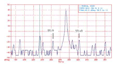
Figure 3. Eccentricity characteristic current harmonics around the fifth component.
IV. CONCLUSIONS
In this paper, we present a practical approach to the detection of static and dynamic eccentricity in cage induction motors fed by frequency converter using line current spectral analysis.
We have described how mixed eccentricity can be detected, observing the sidebands of the eccentricity related harmonics and these results have been experimentally verified analysing real spectra of faulty machines fed by frequency converter.
It is important to highlight that the proposed method has, as well as a theoretical base, a fundamentally intuitive approach, specially adapted for the maintenance personnel, because eccentricity is detected observing the spectra. So it is not necessary to perform precise measures or further spectral analysis.
REFERENCES
[1] Dorrell, D.G.; Thomson, W.T.; Roach, S., “Analysis of Airgap Flux, Current and Vibration Signals as a Function of the Combination of Static and Dynamic Airgap Eccentricity in 3-Phase Induction Motors”, IEEE Trans. Ind. Appl., Vol 33, Nє 1, Jan/Feb. 1997, pp. 24-34.
[2] Cameron, J.R.; Thomson, W.T.; Dow, A.B., “Vibration and current monitoring for detecting airgap eccentricity in large induction motors”, IEE Proceedings, Vol 133, Pt. B, May 1986, pp. 155-163.
[3] Yang, S.J., “Low-Noise Electrical Motors”, Oxford University Press, New York, 1981.
[4] Staurov, A.; Penman, J, “The on-line quantification of air gap eccentricity in induction motors”, International Conference on Electric Machines and Drives, ICEM 94, Paris 1994, pp. 261-265.