|
1.Analysis of safety and reliability of objects of
building materials.
1.1 Problems of reliability and safety providing for
equipment of enterprises of.
1.2 Literary analysis of existent methods of reliability providing
and safety providing for equipment of enterprises build materials industry
1.2.1Applied methods of safety providing
1.2.2 New methods of reliability providing
2.Development of the system of
calculation of equipment reliability and safety equipment, concept of
degradation.
2.1Development of criteria for estimation of equipment degradation.
2.2Structural analysis of equipment
2.3Determination of
reliability and remaining resource of equipment elements by «PAUK-CIW» method.
2.4Determination of reliability and safety of equipment
3. Research of equipment degradation.
3.1 Research of degradation friction press at «Kondratievsk factory
of fireproof materials.
3.2 Research of wage loading mechanisms degradation.
4.Economic substantiation.
The existent methods of calculation of reliability and safety of the technical systems are mainly based on statistical approach, if the state prognosis is executed when we have enough information from the technical objects of the same type.
Today there is not effective accumulation about the systems exploitation at our industrial enterprises.
Corresponding information about repairs, breakages, mechanism refusals, reasons and types of destructions can be found, but it is not systematized. Although statistical approach has its advantages, it does not allow to take into account the work conditions of concrete equipment unit, results of the prepare affecting on the systems, replacement of elements, strengthening of modernization.
All this explaines the necessity of the development of the informative system allowing accumulating and treatment information, which is about changes of properties of the technical system during the exploitation process and repairs. Treatment of information allows not only to prognoses the state of every element of the concrete technical system at the definet moment of time, but also determine the state of the whole system.
During the process of life cycle of the technical system we observe changes of properties of its elements, reasons of these changes are the degradations in the pair of frictions, corrosion, whish is a result of influence of external and working environments, changes of physical, mechanical and chemical properties of materials because of ununiform structure of materials, internal tension, lowered temperatures, pressure and etc.(with another words it means degradations
of the system). The analyses shows that the change of elements properties and as a result- of the connections, results in a change of materials properties results in a change of degradation speed. In practice control of the state of technical system is taken to monitoring of elements “geometry” of this system.
It is necessary to know the initials and maximum values of parameters of system elements in order to fulfil such kind of the concept of attended and unattended elements. A maximum value of parameters of the attended elements is determined from admittances of its making and exploitation. A maximum value of the unattended parameters is set taking into account the durability and inflexibility and etc. The value of parameter of element of the initial moment we
take as 100%, the maximum value of parametr corresponds a repair size.
We enter a criterion for the estimation of the whole system, this criterion is founded on the object comparison method “PAUK-CIW” (abbreviation of “CIW” is formed from the name of Central Institute of Welding, which this method has developed).
The method of “PAUK CIW” is an evident diagram, built in the polar co-ordinates. Axes, which the values of parameters are marked on are directed on radiuses from the center of circumference to periphery. There is an example, explaining this method, on the 1 scheme. It allows to carry out comparison of the same characterizing parameters of object.
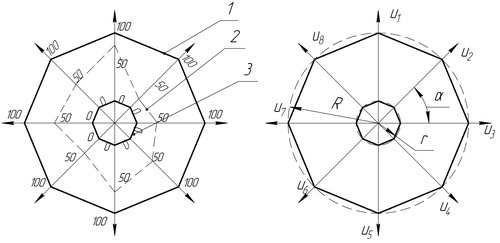
Scheme 1- for the calculation of change of system's element parameters
- the initial state of the system;s element
- current state of system's element
- the maximum state of the system's element
Аll data are put on the plot (in percents), every parameter is equal 100% at the initial moment. The figure is built in such a way in oroler to consern to the possible state of element of the technical system. The figure is built, using the minimum values of every parameter. Information about parameters must come from a working objects and is marked on the plot, what corresponds to current state of the system element.
Consequently, when the figure number 2 cross the figure number 3 at least in one point, it is necessary to make repairs or to do something in order to renew parameters.
The area of the figure 1 is a 100% resource, the area of the figure 3 is the minimum resource of element of the technical system(exploitation of equipment is not recommended).
The calculation of the state of the technical system’s element follows on the below offered methodic.
Entered restrictions and assumptions:
- a quantity of the controled parameters for one element of the technical system must be more than two;
- the controlled parameter must have a quantitative estimation;
- a parameter is put on the ax of the plot (in percents).
If to take into account all accepted assumption it is clear that the calculation of area is taken to determination of triangls area with their further adding up.
The got figure and its area is accounted as a correct polygon (scheme 1b) at the initial moment of the time when all parameters are put on the axes.
The area of polygon or initial state of the element is calculated according to the formula:

Where  -is area of correct polygon -is area of correct polygon
n- is a quantity of parameters
R- is a radius of describe circule and is equal to the syngle segment, which is put on the axes of the plot.
 - is the area of polygon, is calculated according to the formula: - is the area of polygon, is calculated according to the formula:

 -is a central coner, which is calculated according to the formula: -is a central coner, which is calculated according to the formula:

the area of the initial polygon is standard and it is assumed that all parameters are within the limits of norm. The area and state and resource is equal to 100%. The further change of parameters the change of type of the plot and the area of polygon is calculated triangles as a sum of area results in according to the formula:

where ui is a size of parameter;
Consequently the area of polygon of actual state of object is calculated on a formula:

Differences of indexes of СН and СФ and will be named the parameter of degradation

As a results we get the value of the degradation parameter. It shows how element of the technical system changed the properties (%) during the central interval of time.
After determination of the state of each element of the system the estimation of whole system is executed taking into account connections. But for this it is necessary to get the proper criteria.
At present the accumulation is conducted using SUBD (the system of leading of information), based and capture of data both automatically using microcontrollerov and sensors and adding of information by operators. To the bases using of computer systems considerably reduces labour intensiveness and increases speed of calculation of the actual technical systems.
|