Dovgan Alexander.
Title of master thesis:
"Development and studying of power-saving transformer for a management of the automated electric drive for mining hoisting plant".
Table of contents.
Introduction
A modern mining enterprise is the most complex interconnected complex of different processes of productions. Their functioning is based on the use of high-performance automated machines. Intrinsically automatic control in one or another degree is presented in all basic and ancillary operations: coal output, transporting and hoisting of minerals, construction of development heading, ventilation, pumping. Pumping processes, ventilation and hoisting, can be controlled automatically.
1. Information in common
1.1.A purpose of work is cutting of reactive-power consumption and increase of power-factor of electric drive for mining hoisting plant.
Tasks of work – to analyse operation of transformer for the direct current motor according to the purpose above, to select advantages and disadvantages of the basic electric drive management system, to develop a new system on a base of initial taking into account its advantages and removing its failings.
1.2. Actuality of theme.
Perfection of technological processes and introduction of new, more effective machines becomes impossible without the use of the automatic control systems and modern computer aids.Currently a lot of attention is paid to power-saving technologies because the task of power independence of Ukraine from countries, owning oil and gas resources, is not solved yet. Thus, improving the indexes of energy consumption it is possible to decrease this dependence.
In master's degree work I am trying to solve the problem of excessive energy consumption of mining hoisting plant with the direct current motor, what at same time appreciably influences the energy consumption of all the mine.
1.3. Scientific novelty
For justification of scientific novelty I’d like to analyse the existent technical solutions in area of perfection of electric drive management systems.1.3.1. System: the controlled rectifier – motor (CR-M).
Direct voltage variation is accomplished by the switch activation corner control in conducting part of alternating voltage period and has it’s features.
In realization of electric drive for mining hoisting plant by system of CR-M one of the following two circuits is applied:
- with two power thyristor converter, each of which propagates the motor armature current of mutually opposite direction (sign);
- with one power thyristor converter and reverse in an armature circuit or reverse of excitation flux.
In a chart with two power thyristor converter the latter can be connected in a crossed or opposite- parallel chart. The most economical and complete chart is opposite-parallel, because in a crossed chart a triple-wound transformer is used (20% more powerful). It has a substantial value, especially at large power of electrical equipment.
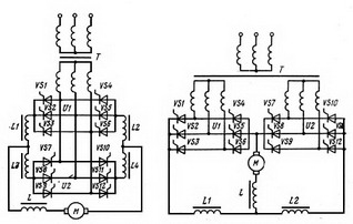
Figure 1 - Crossed and opposite-parallel connection of thyristor converters.
Converter management in the chart of the opposite-parallel connection of power thyristor converters can be joint or separate. At a joint management one controlled converter works in the rectifier mode and other is prepared to the inverter work mode. At a separate converter management signals are given separately. At such management one of converters is always locked and management signals are not given to it. This fully eliminates the possibility of circulating currents appearance, and the necessity in compensator balancing coil disappears, and also the power of transformer is fully used .
An operation mode of separate management drive changes by stopping giving management signals to the converter, for example, working in the rectifier mode. After loosing current in an armature circuit a managing signal is given to the second transformer with the angle of adjusting of ?>?/2, providing it in the inverter mode.
The electric drive systems with an excitation flux reverse have a less dimension of electrical equipment in comparison with an opposite-parallel chart, but have worse dynamic indexes, because the time of reverse increases because of inertance of winding.
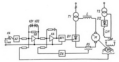
Figure 2 – Schematic circuit of hoisting plant electric drive CR-M system.
Principle of circuit’s work is given here.
An efficiency factor of thyristor rectifier includes product of transformer and switches efficiency factors. Efficiency factor of transformer of middle and large power at nominal loading is approximately 0,95-0,98. An efficiency factor of thyristor rectifier is defined by a direct voltage loss on him, which for one thyristor is about 1-1,2 V. Therefore general efficiency factor of rectifier at the nominal loading for power 50-100 kW is about 0,9-0,92. Rectifier efficiency factor increases with increasing power. A power factor of thyiristor rectifier is calculated by a formula:

which shows, that power-factor slumps with growth of opening angle of thyristors, what is the substantial lack of circuits with a thyristor rectifier. Because of falling of power factor the hoisting plan consumes a reactive-power from a network.
Armature voltage variation can be implemented by pulse method, when the notor is periodically connected and disconnected to the power source. In the period of disconnecting an electric drive continues working due to the stored kinetic and electromagnetic energy.
The connection circuit of direct current motor with separate excitation with the voltage pulse control given on a fig. 3, a. Diode V, bypassing the motor armature, creates a chain for armature current flowing under an action EMF of self-induction, arising in inductance of armature winding in the period of disconnected state of the key K. This creates the conditions for the flowing of armature current, that substantially cuts it’s pulsations and removes commutation overstrains on the key K and armature winding.
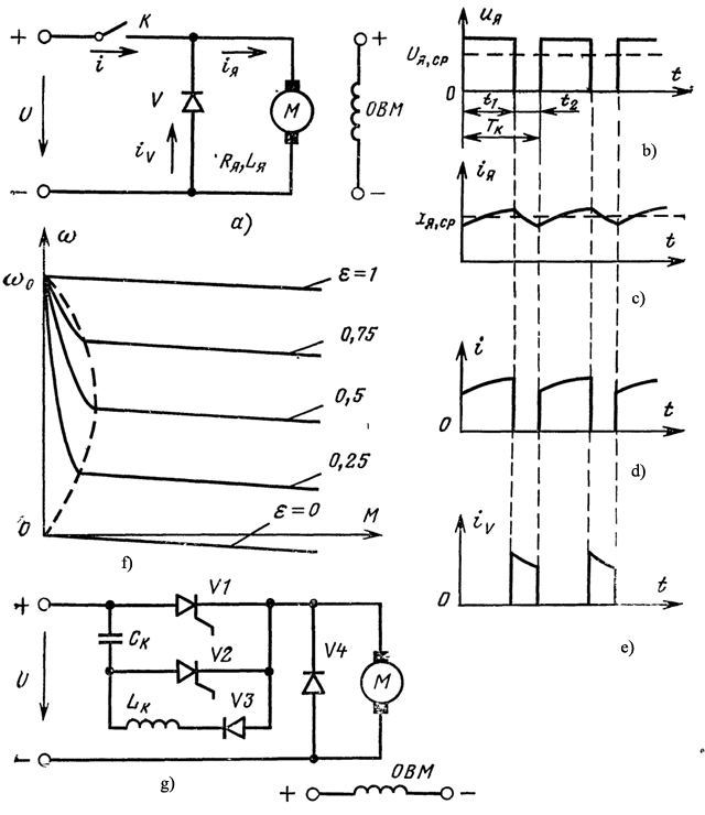
Figure 3 – Communication circuit of motor at motor armature voltage pulse control (a), diagrams of voltage (b), of currents (c, d, e) and mechanical characteristic (f) at time-proportional control and circuit of thyristor regulator.
Among all known types of pulse control for variation of angular velocity primary application was found by the time-proportional control of voltage, at which the period of commutation Tk (frequency) remains permanent, and time tx of the closed state of the key K changes – duty factor ε = t1/T k.
The average value of armature voltage at TPC is equal:
Uaav = εU
where U is unchanging voltage of network. The diagrams of currents are shown on a fig. 3, в-д. Equation of mechanical characteristic of motor looks like for the average values of angular velocity and moment:

where follow from, that an angular velocity can be varied in wide limits, changing rigidity of mechanical characteristics at angular velocity regulation is permanent and equal to rigidity of natural characteristic. It is a merit of this method of angular velocity regulation. However high rigidity is proper to characteristics only in area of continuous armature current. If in the period of the key K closed state the armature current manages to go down to zero and in the curve of current is a pause, the interruptible current mode takes place, where rigidity of mechanical characteristic (fig. 3, f) slumps. The basic mean of interruptible current constriction, diminishing of armature currents (moment) and angular velocity pulsation in relation to an average value and, consequently, additional losses in armature windings is increasing of key commutation frequency. Usually commutation frequency is 800-1200 Hz. Growth of losses in the key (transistor, thyristor) and it’s maximum dynamic parameters interferes with frequency growth.
For realization of the considered method of voltage variation either transistors, workings in key mode, or thyristors can be used.
The circuit of electric drive with the thyristor key is given on fig.3, g. This key works the same as in a chart on a fig. 3, d, but in this case there is no necessity in additional power source for the preliminary charge of switching capacitor Сk, which is preliminary charged from a network through switching thyristor V2 and motor armature. With the switching of thyristor VI occurs the power supply of motor armature, shutdown of thyristor V2 and oscillating recharging of capacitor Ck through the reactor Lk, thyristor VI and diode V3.
At motor connection on the circuit of fig. 3 a, g it can work only in traction mode and mode of dynamic braking (at active moment character), and the reverse of motor is possible only by means of excitation current reverse. But there is a lot of circuits of TPC of voltage (motor angular velocity), allowing motor working in all modes (at a direct current network or accumulator supply) and implement it’s contactless reverse on the chain of armature.
In my master degree work I’ve taken the CR–M as basic control system. The system CR–M with a thyristor converter has the substantial lack – a change of power factor while speed variation. Because of cosφ change the consumption of reactive-power of direct current motor changes which power is as large as thousands kW. Thus, the system CR–M requires an improvement which can be implemented by means of element base change and change of rectifier management principle, that is uniting both the systems considered earlier.
A rectifier is constructed with IGBT on the base of Larionov circuit. Such rectifier is named «active». Management principle is TPC (described in part 1.3.2). This method of rectifier management allows practically to eliminate a consumption of reactive power by hoisting plant, set the level of cos?? near 1, and thus to improve the efficiency factor of plant.
2. Survey information:
Analysing the up to date theme condition in a department, in Ukraine and over the world, I came to conclusion, that the theme studied by me is new enough and actual for our university and all over the world in whole.3. Final information
3.1. Review of present and planned results
The task of development of electric drive management circuit is performed in three stages:
- development of structure circuit;
- development of functional circuit;
- development of schematic circuit.
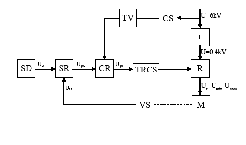
Figure 4. – The structure circuit of the automated electric drive. 12 frames, repeat 10 times, period 0.3c
Principle of this chart action is based on principle of action of the system CR–M. Two measuring current transformers are used as a sensor of current, which give out a signal about the work-load of skip to the current regulator. This way an adjustment of managing voltage for switches and speed of skip is implemented. A speed feedback is implemented by direct current accelerometer. A difference between this chart and CR–M with a thyristor rectifier is in a presence of TRCS instead of pulse-phase control system (PPCS) and active rectifier, which consists not of 12, but of 6 keys. Such rectifier control turns out more effective due to absence of voltage phase displacement. A power-factor of such rectifier can be supported near the level of 1. The plant reactive power consumption from the network can be reduced to the minimum, what was the substantial lack of thyristor rectifier. Thus, increasing a power factor of rectifier it is possible to increase efficiency factor of hoisting plant in whole.
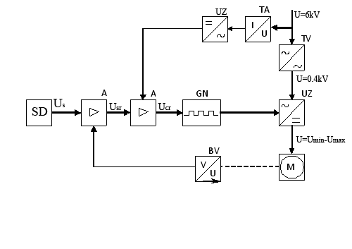
Figure 5. – The functional diagram of automated electric drive of MHP with system of CR–M.
On a fig. 4 the structure circuit of the automated electric drive with system CR–M is presented. On a chart the following abbreviations are accepted: SD – setting device, SR – speed regulator; CR – current regulator, TRCS –time-proportional control system; VS velocity sensor (accelerometer); CS – current sensor (current transformer), R – rectifier, T – power transformer; TV – voltage transformer; M is motor. Continuous lines identify electric connections, dotted - mechanical.
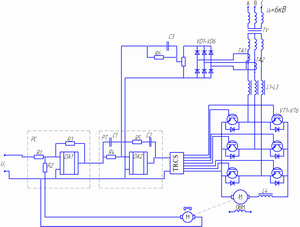
Figure 6 – Principle circuit of electric drive for the mining hoisting plant.
On a figure 6 there is principle chart of electric drive for the mining hoisting plant given. The chart was developed by me on basis of CR–M chart, offered in part 1.3.1 (figure 2).
The drive principle chart is built on the basis of structure and functional diagrams, resulted higher. Principle chart consists of power and control circuit. Power part consists of power transformer, voltage rectifier and motor. A transformer is being chosen depending on engine power. Transformer - so- called active rectifier – is built by the of Larionov circuit on IGBT and smoothing reactors in each phase. Transistors are chosen from the calculation of half of nominal current passing (nominal motor current) with a reserve on thermal stability, reactors are being chosen to the nominal current of engine. The reactor is additionally put into the armature chain for smoothing the current surge in armature.
By the moment of site creation I have solved the task of development of principal chart of electric drive for MHP. Planned results by the defence of master’s degree work:
- development of principle chart of TRCS;
- modeling of direct current motor starting process with a thyristor and active rectifier and gaining the graphs of power factor and reactive power change during starting of DCM.
3.2. Conclusions.
Aims and tasks of master's degree work were formulated in the abstract of thesis, actuality of theme is grounded. For the ground of master's degree work theme scientific novelty the analysis of existent solutions was conducted in area of automation and direct current electric drive control.
As a result of existent solutions review for this topic in DonNTU, in Ukraine and over the world the conclusion was made about actuality of theme and that it is not fully studied yet.
In a part 3there are up to date results presented and tasks which are necessary to be solved by the defence of master's degree work are formulated.
3.3. Referals.
- Правицкий Н.К. Рудничные подъёмные установки - М.- 1963. – 416 с.
- Малиновский А. К. Автоматизированный электропривод машин и установок шахт и рудников. – М.: Недра, 1987. – 278 с.
- Чиликин М.Г., Сандлер А.С. Общий курс электропривода. – М.: Энергоатомиздат, 1981. 576.
- Герман-Галкин Р.Б. Силовая электроника. – С.-Пб., 2002г.
- Гаврилов П.Д., Гимельштейн Л.Я., Медведев А.Е. Автоматизация производственных процессов. Учебник для вузов. М.: Недра, 1985. – 215с.
- Батицкий В.А., Куроедов В.И., Рыжков А.А. Автоматизация производственных процессов и АСУТП в горной промышленности. – М.: Недра, 1991. – 303с.
- Католиков В.Е., Динкель А.Д., Седунин А.М. Автоматизированный электропривод подъёмных установок глубоких шахт.- М.: Недра, 1983.- 270 с.
- Тиристорный электропривод рудничного подъёма / Динкель А.Д., Католиков В.Е., Петренко В.И., Ковалёв А.М.- М.: Недра, 1977.- 312 с.
- Лебедев Е.Д., Неймарк В.Е. и др. Управление вентильными электроприводами постоянного тока.- М.: Энергия, 1970.- 200 с. 10.