
UDC 622.232.72
Automation of technologic objects and processes. Searching for young scientists. Collection of scientific article VII International technical-scientific conference of graduate students and students in Donetsk 26-28 april 2007. – Donetsk: DonNTU, 2007.
Researches of the outrigger feeding system that were made earlier were orientated on the automation of the main (pulling) driver. But with the increasing of the lengths of pit-faces and increase in efficiency of treating pit-faces for efficiency improvement of existing automation treating machines system it was necessary to automate two drivers of the outrigger feeding system. It will help to use the second (tightened) driver of feeding system.
Authors led work to determine and to specify optimal parameters of the automated apparatus in case of simultaneous control of both feeding system drivers. For making researches there was a functional scheme of outrigger feedings system (OFS) of treating machine with the control apparatus and mathematical model describing it's work.
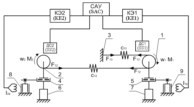
The functional system of researched model of OFS of treating machine with control apparatus is shown on the pic.1

Picture 1 - The functional scheme of OFS of treating machine substitution
It consist of the main (pulling) 1 and auxiliary (tightened) 2 electronic feeding drivers with suitable electromagnetic brakes of sliding EBS 9,8. Drivers 1 and 2 are linked between themselves and machine 3 with pull chain with working part C13 and free part - C12 [1]. The rotation frequency of pulling driver is measured in speed sensor SS1, pulling sensor SS2. Model consist also electric motor of the main 7 and tightened 6 electric drives with planetary reducer 5 and 4 accordingly. Signal of the back connection in speed moves from speed sensors (SS1 and SS2) into system of automatic control SAC where signals for control of key elements KE1 and KE2 are formed, with a help of which current feeding comes to winding EBS excitation.
The model of pulling and tightened feeding EBS drivers are described in a following equations sets:

where  - is a moment on drive axis star from driver side;
M - is a maximal admission socket moment; V0 - is a nominal linear speed of drive star, accordingly
to the maximal speed of machine's moving iob1(ob2) - is current in excitation EBS winding;
a, b - are coefficients of drive star;
M/Rpz = F - maximal effort, transmitted by EBS; M1(2)/Rpz = F1(2) -
is current effort, transmitted by electric driver
The system of differential equations, describing mathematical model of feeding drivers EBS and control apparatus were solved jointly with a help of Runge-Kutt method and MathCAD.
The particular case of differential equation system solution is shown on the picture 2.
Picture 2 - Diagrams of the differential equations system
(animation: 7 frame, 10 cycles, size 40,5Kb)
Parameters received during the analysis will be taken into account by automatic control system projecting for treating machine, that are used in mine "Krasnoarmeyskaya Zapadnaya". Further researches in this area will let to improve an existing automation apparatus, that will bring to efficiency increasing of OFS and mine productivity of the treating mine in common.
