Полный текст статьи находится по адресу http://www.mgu.bg/annual/public_html/2006/bg/svityk3/dokladi_pdf/vatavu.pdf
CONSTRUCTIVE AND CALCULUS PARTICULARITIES FOR THE HYDRAULIC PROPS OF POWERED ROOF SUPPORT
Sorin Vatavu 1, Niculina Vatavu 2
1 University of Petrosani, vatavu@upet.ro, sorinvatavu57@yahoo.com
2 INSEMEX Petrosani, niculina.vatavu@gmail.com
Constructive and operating particularities of the hydraulic props for the powered roof support
The hydraulic prop represents the active element of the metallic roof support in faces, this fulfilling the bearing strength function, as a consequence of the resistance it opposes to the geodetical pressure generated by the roof rocks.
The hydraulic prop consists in a power cylinder that operates commonly with a open controlled unlocking valve (having a retain function – this is the reason it is called hydraulic padlock) and with a safety valve; the operating command being given from a distributor; the mentioned apparatus may be individual or assembled in a hydraulic block and connected with the prop in a sole circuit. In the case of the powered roof support section, the hydraulic props are used in pairs or four at a time.
The hydraulic system of the powered roof support comprises mainly the same components as the individual hydraulic props, the difference consisting in the fact that the valve’s assembly is not an integrant part of the prop, but represents, together with the power hydraulic cylinder, a complex structure that defines the prop.
In fig. 1 are shown the hydraulic schemes of the SMA-2 (a) and CMA standard (b) types of powered roof supports; the reference points have the following signification: 1- hydraulic cylinders; 2- safety valves; 3- hydraulically controlled unlocking valves; 4- manometers; 5- distributor; 7- cocks; SDD- double unlocking valve; AMM-monoblock multiple apparatus.
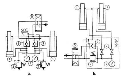
Fig. 1. Hydraulic schemes of the SMA-2 (a) and CMA standard (b) types of powered roof supports
Taking into account the principle of maximum opening accomplished, the powered roof support’s props are divided into two categories: a. with one step: b. with two or three steps.
The first category equipped supports used in conditions of seams having medium or big thickness, their maximum openings is attained solely hydraulically, or with mechanical extensions: the extensions are used in cases when the working height of powered roof support attained through the simple cylinder is lesser than the working face’s height.
The second category equipped supports for thin and medium thickness seams, lately arising the tendency of using on a larger scale the props having two opening steps, those offering better possibilities of adjusting to the seam thickness variations.
Taking into account the bearing strength at roof load, the powered roof support’s props may be:
• High bearing strength props (500 – 3000 kN): it’s used a number of one or two or four in one section and they have a large diameter;
• Low bearing strength props (< 500 kN): for the light types of powered roof supports.
The calculus and energetic of the hydraulic prop
The diagram of hydraulic prop operating (Vatavu et al. 1999) is shown in fig. 2 and it points out the four mentioned steps.

Fig. 2. The diagram of hydraulic prop operating
As a result of feeding with pressurized
liquid, the individual hydraulic prop extends and develops the opening force ![]() ,
,
![]() , (1)
, (1)
that is required for uplifting towards the roof the prop’s telescope and the roof beam, which are components with constant weights:
![]() , (2)
, (2)
in formula (1) Fp represents the force developed by the piston
having the Ds diameter
when acting the feeding pressure pS, ![]() ,
, ![]() – the inner friction force due
to the piston’s sealing system, proportional to the feeding pressure,
– the inner friction force due
to the piston’s sealing system, proportional to the feeding pressure, ![]() ,
, ![]() is the mechanic
efficiency of the prop.
is the mechanic
efficiency of the prop.
In order for the piston to develop the force FdS , the pump must generate the pressure
 , (3)
, (3)
where ![]() represents the hydraulic
efficiency of the pump-prop connecting circuit.
represents the hydraulic
efficiency of the pump-prop connecting circuit.
When the prop places the roof beam on the roof, the feeding pressure attains the value pmaxP that is regulated through the adjustment of the safety valve in the feeding hydraulic assembly, for which the force developed in the prop means in fact prop’s pre-fastening force:
 . (4)
. (4)
On the operating characteristic shown in fig. 2, the ordinate OA corresponds to pre-locking force, and a point that is inferior to A corresponds to the opening force.
After the hydraulic prop pre-locking with the force FiS and after feeding cut off, the one way/sense valve 3 (fig. 1) closes the cavity under the prop’s piston. Mine pressure acting generate the lowering of roof rocks level: this results in increased pressure under the piston, elastic compression of the emulsion column and cylinder walls swelling, and the piston carries out an elastic withdrawal having the stroke ∆s*. The value of elastic slide of piston is given by the sum of two components,
![]() (5)
(5)
the first due to elastic compression of the emulsion column under the piston and the other due to the increased diameter of the cylinder as the result of the elastic deformation of the wall.
The regime of strength elastic increase determines the time t* needed to attain the rated strength after prop pre-locking,
![]() (6)
(6)
where ![]() is the
mean value of lowering speed of roof rocks; during this interval, the force
developed by the piston increases at the value
is the
mean value of lowering speed of roof rocks; during this interval, the force
developed by the piston increases at the value ![]() ,
and the resistance opposed by prop to the roof rocks increases at the value FmaxS (segment AB).
,
and the resistance opposed by prop to the roof rocks increases at the value FmaxS (segment AB).
When value ∆s* is attained, the pressure under the piston reaches the value pmaxS – which ensures the prop’s safety valve entering into operation. Beginning from this operation moment, it passes into the steady strength regime, the prop develops the maximum force, named nominal strength, this corresponds to the segment BC and the formula:
 (7)
(7)
in this situation, the mechanic efficiency ηmS is constant, due to the fact that it depends on the value of the pression developed under the piston, that is settled through the adjustment of the safety valve 3 (fig. 1).
The work regime that allows developing the nominal strength is reached as a result of intermittent operating of safety valve 3. When operating in steady strength regime, which corresponds to period trn , the prop’s height decreases with a value determined by the amount of emulsion evacuated from the cavity under the piston through the safety valve.
In order for the support to step, it is necessary to unload the hydraulic props: in this phase of the work technology, the prop is unstressed by its load, the operation (segment CD) being carried out in the time td; after support stepping, the prop is extended and the cycle shown repeats.
The graph OABCD is named the ideal operating characteristic of the hydraulic prop and, if admitted the lowering speed of roof as a constant, then its surface express the resisting activity of the hydraulic prop towards the roof rocks lowering.
It must be taken into account the fact that, in most cases, the real operating characteristic may differ from the ideal one shown in fig. 2.
From the point of view of improving the interaction between the support and the roof rocks it’s advisable that the hydraulic prop’s pre-tensioning to get as near as possible to the value of the nominal working strength. For the supports used in mine exploitations in our country, the pressures of feeding the hydraulic props vary between 15 up to 30 MPa.
The working regime specific for long term operating of the safety valve in the hydraulic props is the one which can ensure the smaller and the most even lowering of roof rocks, with a mean speed value of a few millimetres per hour, thus determining the smallest flow evacuated.
Conclusions
Ensuring a normal and efficient working of
the support supposes the pre-locking force of the hydraulic props to have a
value as closest as possible to the one of the force developed during the
nominal strength regime: increasing the maximum feeding pressure reduces the
difference between the operating pressure of the safety valve and accordingly
reduces the value of elastic sliding ![]() and time t* to pass into the constant
strength regime, by this radically improving interaction between support and
face roof.
and time t* to pass into the constant
strength regime, by this radically improving interaction between support and
face roof.
Choosing the safety valve in close correlation with the roof rocks characteristics has a special importance, since, in the rock-support system, it determines, on one hand, the resistance opposed by prop at roof lowering, and, on the other hand, it ensures the integrity of roof rocks.
The principles of calculus presented allow the assessment of dynamic parameters both those at feeding and those developed, fact that allows a general evaluation of the energetical performances of the hydraulic props, respectively for the support.
References
[Pătraşcu P., Vătavu S. 1997. Particularită i privind functionarea şi încercarea supapelor de siguran ă pentru stâlpii hidraulici de sus inere a lucrărilor miniere. In: Lucrările Conferin ei Na ionale de Termotehnică, edi ia a VII-a, vol. 3, Braşov, 149 – 154.
Vătavu S., Pătraşcu P., Vătavu N. 1999. Some Considerations Regarding Hydraulic Supporting Props Working in Elastic Increase of Resistance Conditions. In: Annals of University of Petroşani, Mechanical Engineering, vol. 1(XXVIII), 79 – 82.
Перевод осуществил Ульянов Е. А.
КОНСТРУКТИВНЫЕ И РАСЧЕТНЫЕ ОСОБЕННОСТИ ГИДРОСТОЕК ГИДРОКРЕПИ
Sorin Vatavu1, Niculina Vatavu2
1 University of Petrosani, vatavu@upet.ro, sorinvatavu57@yahoo.com
2 INSEMEX Petrosani, niculina.vatavu@gmail.com
Конструктивные и рабочие особенности гидравлических стоек крепи
Гидростойка представляет собой активный элемент металлической крепи для поддержания кровли, она выполняет силовые функции, вступая в сопротивление геодезическому давлению, вызванному породами кровли.
Гидравлическая стойка состоит из силового гидроцилиндра, функционирующего обычно при открытии управляемого обратного клапана (который выполняет функцию удерживания и называется гидрозамком), и с предохранительным клапаном. Управляющая команда поступает из распределителя. Указанный аппарат может быть индивидуальным или собранным в гидравлический блок, соединенный со стойкой в одну сеть. В секциях крепи, гидравлические стойки используются парами или четыре одновременно.
Гидравлическая система крепи включает в себя главным образом те же компоненты, что и индивидуальные гидравлические стойки, различие состоит в том, что клапан не является составной частью стойки, но представляет, вместе с силовым гидравлическим цилиндром, полноценную систему, называемую стойкой.
На рис. 1 показаны гидравлические схемы крепей стандартов SMA-2 (a) и CMA (b); номерами на рисунках обозначено следующее: 1-гидравлические цилиндры; 2-предохранительные клапаны; 3-обратные клапаны с гидравлическим управлением; 4-манометры; 5-распределители; 7-вентили; SDD-сдвоенный обратный клапан; AMM-гидроблок стойки.
Рис. 1. Гидравлические схемы крепей стандартов SMA-2 (a) и CMA (b)
Принимая во внимание принцип максимального раздвижения, гидравлические стойки делятся на две категории: a) одинарной раздвижности; b) двойной (и более) раздвижности.
Первая категория гидравлических стоек в гидрокрепях используется в случае разработки пластов средней и большой мощности, они достигают максимального открытия исключительно гидравлически или с механическими удлинителями, которые используются в случаях, когда рабочая высота крепи, распертой гидроцилиндром, меньше высоты забоя.
Вторая категория гидравлических стоек используется в случае тонких пластов и пластов средней мощности. В последнее время появилась тенденция широкого использования стоек, имеющих двойную раздвижность, которые обладают лучшими возможностями настройки к изменениям мощности пласта.
Принимая во внимание силу давления кровли, гидравлические стойки могут быть:
• Стойки с высокой опорной силой (500 – 3000 кН): имеют большой диаметр и устанавливаются по 1, 2 или 4 в одну секцию;
• Стойки с низкой опорной силой (<500 кН): для облегченных типов гидрокрепей.
Расчет гидравлической стойки
Диаграмма рабочей характеристики гидравлической стойки (Vatavu и др. 1999) изображена на рис. 2, в ней выделяют четыре участка.
Рис. 2. Диаграмма рабочей характеристики гидравлической стойки
В результате подачи жидкости в гидравлическую
стойку, она раздвигается, преодолевая силу ![]() :
:
![]() , (1)
, (1)
Она требуется для поднятия к кровле телескопической опоры вместе с верхняком, которые являются компонентами с постоянными весами:

В формуле (1)
Fp
представляет силу, развиваемую поршнем, имеющим диаметр Ds, на
который действует давление ps, ![]() ,
, ![]() –
сила внутреннего трения, которая вызвана герметизацией поршня и
пропорциональная подводимому давлению
–
сила внутреннего трения, которая вызвана герметизацией поршня и
пропорциональная подводимому давлению ![]() ,
, ![]() -
механический КПД гидростойки.
-
механический КПД гидростойки.
Чтобы поршень мог развить силу FdS, насосу необходимо создать давление:
где ![]() -
гидравлический КПД сети насос-гидростойка.
-
гидравлический КПД сети насос-гидростойка.
Когда стойка прижимает верхняк к кровле, питающее давление достигает значения pmaxP, определяемое настройкой предохранительного клапана, находящегося на питающей гидравлической магистрали. Сила давления в гидравлической стойке будет равна:
На рабочей характеристике, изображенной на рис.2, ордината OA соответствует силе начального распора, а точки, лежащие ниже т. A, соответствуют силе открытия.
После того, как гидростойка осуществит начальный распор с силой FiS, обратный клапан 3 (рис. 1) запирается, прекращая подачу жидкости в поршневую полость. Под действием горного давления происходит оседание пород кровли, что приводит к увеличению давления под поршнем, деформациям стенок цилиндра и сжатия эмульсии, а поршень выполняет упругое проседание, имеющее ход ∆s*. Значение упругого скольжения поршня определяется двумя компонентами:

Первая компонента выражает упругое сжатие эмульсии под поршнем, а вторая –увеличение диаметра цилиндра в следствие упругой деформации его стенок.
Режим увеличения упругих сил, определяется временем t*, необходимым для достижения номинальной силы после начального распора стойки

где ![]() - среднее значение скорости оседания
пород кровли; в течение этого интервала, сила создаваемая поршнем увеличится до
- среднее значение скорости оседания
пород кровли; в течение этого интервала, сила создаваемая поршнем увеличится до
![]() , и
сила сопротивление опоры к воздействиям пород кровли увеличится до значения FmaxS
(участок AB).
, и
сила сопротивление опоры к воздействиям пород кровли увеличится до значения FmaxS
(участок AB).
Когда значение ∆s* достигнуто, давление под поршнем достигает значения pmaxS, что вызывает срабатывание предохранительного клапана. Начиная с этого момента, в стойке возникает максимальная сила, которую также именуют номинальной силой, что соответствует на диаграмме участку BC и вычисляется по формуле:
В этом случае, механический КПД ηmS постоянный и зависит от значения давления под поршнем, которое устанавливается предохранительным клапаном 3 (рис. 1).
Режим работы, при котором создается номинальное усилие, достигается в результате периодического срабатывания предохранительного клапана 3. При работе в устойчивом режиме, который длится в течении периода trn, высота стойки уменьшается на величину, определяемую количеством сброшенной эмульсии из поршневой полости через предохранительный клапан.
Для перемещения крепи, необходимо разгрузить гидравлические стойки. На данном этапе работы, стойка разгружается под воздействием нагрузки. Эта операция (участок CD) выполняется в течение времени td. После перемещения крепи, стойка раздвигается и цикл работы повторяется.
Граф OABCD называют идеальной рабочей характеристикой гидравлической стойки. Если принять скорость оседания кровли постоянной, то диаграмма отображает процесс сопротивления гидравлической опоры оседанию пород кровли.
Необходимо принять во внимание тот факт, что в большинстве случаев, реальная рабочая характеристика может отличаться от идеальной, изображенной на рис. 2.
С точки зрения улучшения взаимодействия между крепью и кровлей, желательно чтобы значение силы начального распора гидравлической стойки было как можно ближе к значению номинальной рабочей силы. Для крепей, эксплуатируемых в шахтах нашей страны, питающее давление гидравлических стоек находится в пределах от 15 до 30 МПа.
Рабочий режим, обеспечивающий наименьшее оседание пород кровли (со средней скоростью в несколько миллиметров в час), при котором происходит наименьший сброс потока через клапан, является режимом, обеспечивающим большой срок службы предохранительного клапана.
Заключение
Обеспечение нормальной и эффективной работы
крепи предполагает минимальное отличие значения силы начального распора
гидравлических стоек от значения силы номинального режима. Увеличение
максимального давления питающей жидкости снижает разницу между рабочими
давлениями предохранительного клапана и, соответственно, уменьшается величина
упругого скольжения ![]() и времени t*, необходимого для
перехода в режим с постоянной силой. Это кардинально улучшает взаимодействие
между крепью и кровлей.
и времени t*, необходимого для
перехода в режим с постоянной силой. Это кардинально улучшает взаимодействие
между крепью и кровлей.
Выбор предохранительного клапана, в зависимости от параметров пород кровли, имеет особую важность. С одной стороны этот выбор определяет сопротивление гидравлической крепи оседанию кровли, а с другой стороны – гарантирует целостность пород кровли.
Принципы приведенных расчетов позволяют оценить динамические параметры, которые дают возможность произвести общую оценку энергетической производительности стоек гидравлических крепей.
Ссылки
[Pătraşcu P., Vătavu S. 1997. Particularită i privind functionarea şi încercarea supapelor de siguran ă pentru stâlpii hidraulici de sus inere a lucrărilor miniere. In: Lucrările Conferin ei Na ionale de Termotehnică, edi ia a VII-a, vol. 3, Braşov, 149 – 154.
Vătavu S., Pătraşcu P., Vătavu N. 1999. Some Considerations Regarding Hydraulic Supporting Props Working in Elastic Increase of Resistance Conditions. In: Annals of University of Petroşani, Mechanical Engineering, vol. 1(XXVIII), 79 – 82.