
Unbelievable Visualization Techniques |
Unbelievable Visualization Techniques - IntroductionLearn the powerful cinematic technique of camera mapping to create highly photorealistic and engaging animations. We'll also explore creative compositing techniques within Autodesk VIZ and 3ds Max. We'll enhance the visualization process by embellishing renderings with matte painting techniques and bring static rendering to life. This session will use traditional camera mapping as well as the new Camera Map Per Pixel feature to create unbelievable visualizations that will drop viewers' jaws.Animated Camera MappingThis is a powerful technique to create engaging animations from static stills or context shots. This technique is widely used in cinematic productions to bring life to a static camera shot, or matte painting, by creating the illusion that one is traveling within a 3-D environment when in fact it is only a digitally enhanced 2-D image.The best way to describe this is to imagine a slide projector with the image you wish to walk through being projected onto some basic geometry. The image will only be shown where the light is projected. This means that there would be no image where there are shadows and any object whose surfaces fall away from you (like a sphere or cylinder) would have texture stretching if you would make any exaggerated lateral movement. Once you finish this tutorial, you'll see the limitations this technique has, but you will also see the tremendous power that this technique holds. I've chosen the following royalty-free image to explain.  [Click Here For Large Image] By examining the shot, we can break down our approach by deconstructing the scene into basic shapes. For the most part, the building can be considered to exist on one plane. We'll start here and refine our solution as we progress. The most dominant element is the portico. This consists of the deck, columns and pediment. If we were actually on site viewing this image, we would be able to take several steps to either the left or right to reveal what lies behind the columns. Unfortunately, we are not given this luxury with a still image. This is where other reference shots or our imagination will take over. We'll need to take this image into a photo manipulation program, like Photoshop, to create a modified texture to use for the building. Essentially, we need to get rid of objects in the foreground. With a little digital elbow grease we can create the following image by cloning out what we don’t want. 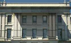 [Click Here For Large Image] Now we’re ready to create the scene. You can choose to create the geometry in real world units so as to place other CG elements within the scene and have them at scale, or you can choose the shot to strictly be an artistic representation of the image. We’ll choose the later in this case since we’re only examining the technique. Start your 3D software and place the image on a 3D plane making sure to preserve the bitmaps aspect ratio. You will have to make the bitmap visible in the viewports in order to continue. This is also where you may wish to try to scale the image in real units to create a fairly accurate scene. To do this, make one of the features (like the window) of known dimension an accurate size. For this tutorial we’re using 3DS MAX but this technique is applicable for any software with camera mapping functionality. You should have something similar to the following. 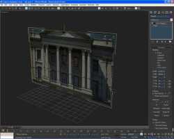 [Click Here For Large Image] Next we’ll use the image as a template to create some basic geometry. The cool thing with this technique is that you don’t have to be totally accurate to create very convincing results. By switching to the front view, we create the following geometry. Note that the plane object we used to create the basic geometry will be used again for the building in the camera map. 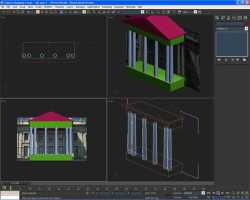 [Click Here For Large Image] Use common sense when creating your geometry. For example, the building in the image has a set depth for the portico. We don’t know the exact measurements from just the image, but we have an idea as to how far the portico may extend. Also be aware of the axis that you may be pulling vertices around in as it is easy to get things “out of square” quite easily by moving in the XY plane as opposed to just the X axis. The geometry doesn’t have to be precise in this stage as it will need to be fudged when we camera match. Now we need to create a camera and match the shot closely, but not necessarily exact. In order to do this, we need to place the image of the building as a viewport background. We can do this in 3DS MAX by selecting an active viewport and pressing alt-b to open the viewport background dialogue. Select File… and choose the same image you used for the plane, making sure to select Match Bitmap. 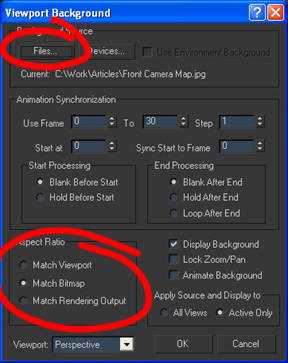 Now we should have an image similar to the following ready to create a camera! 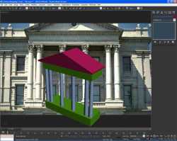 [Click Here For Large Image] Create a target camera and match the perspective as close as possible by playing around with the camera and target positions as well as the focal length if necessary. You’ll notice that things line up close but you’ll still need to fudge the locations more accurately. 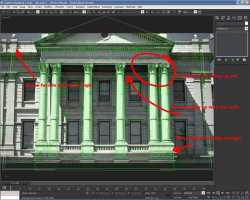 [Click Here For Large Image] Notice that the perspective is not 100% accurate. Don’t let this bother you as it is close enough for this technique. Now look at the patio. The front view showed it to be at the right height but in the camera view, it’s not high enough. Correct this by moving the box up in the Z axis until its height is right. You may also require the height of the box to be taller. You will also need to adjust the size of the plane object that we’re using for the house to fill the frame. Notice the columns are out of whack slightly as well. This can be corrected by moving the columns laterally in the X or Y axis and adjusting their radius and taper. Other things may present themselves such as the ceiling of the portico not matching up with the transition point of the ceiling and wall in the image. Again, play around with location and size and shape of the box in 3D space until you get it matched closer. See the following image after we have fudged everything. 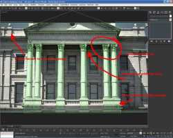 [Click Here For Large Image] The set up is complete and the rest is incredibly simple. We basically have two images to apply as textures to the scene. The only difference is that instead of using traditional UVW maps, we’ll use camera mapping. A little note before we go on. Prior to MAX 7 we had to make sure the geometry was tessellated enough to avoid “texture munching”. That is we needed to have enough vertices to define how accurately the texture will be mapped onto the geometry. If there weren’t enough vertices, the texture was shifted and fragmented and didn’t appear smooth. This was fixed by applying a tessellation modifier with high settings to create enough vertices. Now in MAX 7 there is a camera map per pixel which allows you to use low poly geometry to camera map the image on. We’ll use the camera map per pixel (located as a material type) instead of the camera map modifier (which can be applied like any other modifier in MAX). Select a new material in the material editor and click the diffuse channel slot. This will open the Material/Map browser window where you can choose Camera Map per Pixel as the map type. 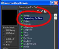 [Click Here For Large Image] Now you’re presented with the following. 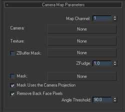 [Click Here For Large Image] Click on the Camera button and select the camera we created for matching the shot. Then click on the texture button to select the image with the Portico removed. Name this material “House” and make the material 100% self illuminated. Copy this material to a vacant slot and name this copied material “Portico”. Now in the Portico material, click the Texture button and choose the original image. Select the plane object and apply the House material. Now select everything else and apply the Portico material to it. We’re almost ready to render the image! The only thing left is to match the rendering output to the original image. In this case the original image was 480x293 pixels. When you render you’ll get the following which looks remarkably similar to the photo.  [Click Here For Large Image] To create an animation, clone the camera we’re using for the camera map as a copy and animate the camera motion moving into the shot. This will give you the parallax and make the image look as though it’s a real video. Now you’ll need to see where the limitations of this technique exist. Start by tweaking the dolly animation to move slightly side to side. You’ll see that there is a range at which this technique holds its own, but if you deviate too far away you’ll see some texture stretching and anomalies from the process. For the most part, if this is to be the background of an animated scene, those discrepancies would vanish since they’re not the focus of the video. If you took more time you could remove any of the discrepancies by adding more detail or maps where needed. Try going through this tutorial 2-3 times (not in a row) to get familiar with the process. Then try it on one of your own photos. After this, you should be comfortable enough to do it quite efficiently. The image and scene for this tutorial took only 15 minutes to create (creating the Photoshop images for textures and setting the scene from start to finish) which gives you quite the bang for the buck! Let’s take a look at an interior scene. I’ve selected this picture to work with. 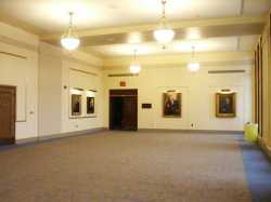 [Click Here For Large Image] Examine the scene to determine how much will need to be modeled. For the most part the room is a box. The only things to be aware of are the light fixtures, the beam on the ceiling and the trash can on the side. When we move through the space, the light fixtures will show parallax and we’ll have to digitally remove them from the scene. We’ll keep the garbage can to show you the limitations. We could easily remove it from the scene or even include it with the geometry but for this exercise we’ll leave it as is. With a little digital elbow grease we can get the following. 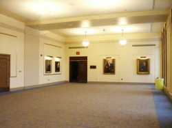 [Click Here For Large Image] We could do the same for the rear lights, but will leave them as is. Now we need to model the room. I wasn’t too concerned with scale, instead I concentrated on proportions. If we needed to, we could easily take some measurements and build the model to scale. As I said previously, the proportions are important. You’ll need to import the image as a background as before, then create a simple box and adjust the perspective view to line up with the vanishing points of the picture. You can use a free camera with the new walkthrough mode to help set this up. Note the red lines showing the geometry. 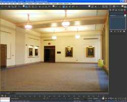 [Click Here For Large Image] To create the lights I simply guessed the size and shape in front view when I drew the basic light shape. Once I positioned the lights to they were suspended from the ceiling, I switched to the camera view and moved them into position. 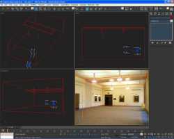 [Click Here For Large Image] Now all the legwork is done! What we need to do is camera map the geometry and we’ll be ready. 1. Open your material editor and select a new material. 2. In the diffuse slot choose the Camera Map Per Pixel map type. 3. For the first material, choose the room with the lights removed in the texture slot. 4. Then select the camera for the camera slot. Apply this material to the room and beam. 1. Now select a new material and repeat the process, this time using the image with the lights. Apply this new material to the light fixture geometry. The only thing to do now is to make both the textures 100% self illuminated since the lighting information is taken from the real world. 2. Make a copy of the camera we used to match the view. We’ll use this to create the animation. Simply animate the new camera moving into the space and you will create the illusion of a 3d walkthrough. We can further develop this by comping in 3D geometry. We’ll go through the process next. To comp in 3D elements, we’ll require a backplate render of our animation. Simply render out the animation to a video or image sequence. We’ll use this as our new background. Simply load the image sequence or video file as our background and place your geometry within the scene. Light it using any method you wish making sure the ground plane is set to matte shadow. Then, render out your animation and the object sits perfectly within the scene! 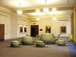 [Click Here For Large Image] Extras [images+videos]:        Scene File Download:Download Scene File [176kb] |
| Источник: http://en.9jcg.com/comm_pages/blog_content-art-53.htm |