Direct3D can handle up to eight sets of texture coordinates per vertex. The format of the vertices you use is created by defining a custom vertex structure. The following structure defines a vertex that contains untransformed position information, as well as a color component.
	struct CUSTOMVERTEX
		{
		FLOAT x, y, z, rhw; // the untransformed, 3D position for the vertex
		DWORD color; // the vertex color
	};
The CUSTOMVERTEX structure consists of the standard vertex position variables X, Y, and Z, but also includes the variable RHW. The RHW value, which stands for Reciprocal of Homogeneous W, tells Direct3D that the vertices that are being used are already in screen coordinates. This value is normally used in fog and clipping calculations and should be set to 1.0.
n o t e Now that the vertex structure is created, the next step is determining the flags that will be sent to the CreateVertexBuffer function as the FVF parameter. Because the CUSTOMVERTEX structure requires non-transformed position information and a color component, the needed flags would be D3DFVF_XYZRHW and D3DFVF_DIFFUSE. The sample code that follows shows a call to CreateVertexBuffer using this vertex structure.
	// a structure for your custom vertex type
	struct CUSTOMVERTEX
	{
		FLOAT x, y, z, rhw; // the untransformed, 3D position for the vertex
		DWORD color; // the vertex color
	};
	// Create the variable to hold the vertex buffer
	LPDIRECT3DVERTEXBUFFER9 buffer = NULL;
	// variable used to hold the return code
	HRESULT hr;
	// Create the vertex buffer
	hr = pd3dDevice->CreateVertexBuffer(
	3*sizeof( CUSTOMVERTEX ),
	0,
	D3DFVF_XYZRHW | D3DFVF_DIFFUSE,
	D3DPOOL_DEFAULT,
	&buffer,
	NULL );
	// Check the return code
	if FAILED ( hr)
	return false;
As you can see, the CUSTOMVERTEX structure is created first, telling Direct3D the type of vertices to use. Next, the call to CreateVertexBuffer creates the actual buffer and stores it in the buffer variable. The first parameter to CreateVertexBuffer, the size of the buffer in bytes, is created with enough space to hold three vertices of type CUSTOMVERTEX. The third parameter, the FVF, is shown as having the flags D3DFVF_XYZRHW and D3DFVF_DIFFUSE being used. The fourth parameter sets the memory pool for this vertex buffer. The value D3DPOOL_DEFAULT is used, which allows the buffer to be created in the most appropriate memory for this type. The final parameter that you have to worry about is the fifth one. This is where you pass in the variable that holds the newly created buffer. After the call to CreateVertexBuffer is complete, make sure to check the return code to confirm that the buffer was created successfully. Loading Data into a Buffer Now that you have a valid vertex buffer, you need to add vertices to it. Before you can place vertices in the buffer, you must lock the memory the buffer is using. After this memory is locked, it is freely available to be written to by your game. Locking the Vertex Buffer Locking the memory used by the vertex buffer allows your application to write to it. At this point, you’ve already defined the vertex buffer and the type of vertices it will hold. The next step is locking the buffer and copying the vertices. Locking of the buffer is accomplished with the Lock function, defined next. HRESULT Lock( UINT OffsetToLock, UINT SizeToLock, VOID **ppbData, DWORD Flags ); The Lock function takes four parameters:
The following code sample shows a normal call to the Lock function. HRESULT hr; VOID* pVertices; // Lock the vertex buffer hr = g_pVB->Lock( 0, 0, ( void** ) &pVertices, 0 ); // Check the return code to make sure the lock was successful if FAILED (hr) return false; The Lock function assumes that you’ve already created a valid vertex buffer. The variable g_pVB refers to this buffer. Copying Vertices to a Vertex Buffer After the vertex buffer is locked, you can freely copy data into the buffer. You can either copy enough vertices to fill the whole buffer, or you can selectively change vertices within the buffer. The next example shows how to use memcpy to copy an array of vertices into a vertex buffer.
	// the customvertex structure
	struct CUSTOMVERTEX
	{
		FLOAT x, y, z, rhw; // the transformed, 3D position for the vertex
		DWORD color; // the vertex color
	};
	// Define the vertices to be used in the buffer
	CUSTOMVERTEX g_Vertices [ ] =
	{
		{320.0f, 50.0f, 0.5f, 1.0f, D3DCOLOR_ARGB (0, 255, 0, 0),},
		{250.0f, 400.0f, 0.5f, 1.0f, D3DCOLOR_ARGB (0, 0, 255, 0),},
		{50.0f, 400.0f, 0.5f, 1.0f, D3DCOLOR_ARGB (0, 0, 0, 255),},
	};
	// Copy the vertices into the vertex buffer
	memcpy( pVertices, g_Vertices, sizeof( g_Vertices ) );
The sample first declares the CUSTOMVERTEX structure. As mentioned before, this structure takes a position vertex as well as a color component. Next, an array of vertices is created. The array, referred to by the g_Vertices variable, holds the vertices to be copied into the buffer. Finally, a call to memcpy is made to copy the vertices into the buffer. The first parameter to memcpy, pVertices, refers to the void pointer that was created during the call to Lock. Unlocking the Vertex Buffer After the vertices have been copied into the buffer, you must unlock the buffer. Unlocking the buffer allows Direct3D to continue processing normally. You can unlock the buffer through the Unlock function, defined here: HRESULT Unlock (VOID); The Unlock function requires no parameters and returns the value of D3D_OK on success. After the vertex buffer is filled with vertices, it’s ready to be drawn to the screen. The SetupVB function that follows takes all the steps from earlier and places them in an easy-to-use function.
	// variable to hold the newly created vertex buffer
	LPDIRECT3DVERTEXBUFFER9 g_pVB = NULL;
	/******************************************************************************
	* SetupVB
	* Creates and fills the vertex buffer
	******************************************************************************/
	HRESULT SetupVB()
	{
		HRESULT hr;
		// Initialize three vertices for rendering a triangle
		CUSTOMVERTEX g_Vertices[] =
		{
			{320.0f, 50.0f, 0.5f, 1.0f, D3DCOLOR_ARGB (0, 255, 0, 0), },
			{250.0f, 400.0f, 0.5f, 1.0f, D3DCOLOR_ARGB (0, 0, 255, 0), },
			{50.0f, 400.0f, 0.5f, 1.0f, D3DCOLOR_ARGB (0, 0, 0, 255), },
		};
		// Create the vertex buffer
		hr = pd3dDevice->CreateVertexBuffer(
		3*sizeof(CUSTOMVERTEX),
		0,
		D3DFVF_XYZRHW|D3DFVF_DIFFUSE,
		D3DPOOL_DEFAULT,
		&g_pVB,
		NULL );
		// Check to make sure that the vertex buffer was
		// created successfully
		if FAILED ( hr )
			return NULL;
		VOID* pVertices;
		// Lock the vertex buffer
		hr = g_pVB->Lock( 0, sizeof(g_Vertices), (void**)&pVertices, 0 );
		// Check to make sure the lock was successful
		if FAILED (hr)
		return E_FAIL;
		// Copy the vertices into the buffer
		memcpy( pVertices, g_Vertices, sizeof(g_Vertices) );
		// Unlock the vertex buffer
		g_pVB->Unlock();
		return S_OK;
	}
The SetupVB function requires that a variable to hold the vertex buffer is defined outside the scope of this function. The variable g_pVB refers to this variable. If the vertex buffer is created and filled successfully, the SetupVB function returns the HRESULT value of S_OK. Drawing the Contents of the Buffer Now that you’ve spent all this time creating the vertex buffer and filling it with vertices, you’re probably wondering when you get to see something on the screen. Well, rendering the vertices within the vertex buffer requires three steps. The first step is setting the stream source, followed by configuring the vertex shader, and then finally drawing the vertices to the screen. These steps are explained in detail in the following sections. Setting the Stream Source Direct3D streams are arrays of component data that consist of multiple elements. The vertex buffer you created earlier is an example of such a stream. Before Direct3D can render a vertex buffer, you must associate the buffer with a data stream. This is accomplished with the function SetStreamSource, defined here: HRESULT SetStreamSource( UINT StreamNumber, IDirect3DVertexBuffer9 *pStreamData, UINT OffsetInBytes, UINT Stride ); SetStreamSource requires four parameters.
An example call to SetStreamSource is shown next: pd3dDevice->SetStreamSource ( 0, buffer, 0, sizeof(CUSTOMVERTEX) ); In this function call to SetStreamSource, the first parameter representing the stream number is set to 0. The second parameter must be a valid pointer to a properly created vertex buffer. The third parameter is set to 0, telling Direct3D to start at the beginning of the stream. The final parameter is the stride of the stream. This is set to the size in bytes of the CUSTOMVERTEX structure. The sizeof function calculates the number of bytes. Setting the Vertex Shader After you set the source for the stream, you must set the vertex shader. The vertex shader tells Direct3D which types of shading to apply. The SetFVF function, defined next, sets up Direct3D to use a fixed vertex function format. HRESULT SetFVF( DWORD FVF ); The SetFVF function requires only one parameter specified by the variable FVF. The FVF parameter accepts a value of type D3DFVF. The following code sample shows how SetFVF is used. HRESULT hr; hr = pd3dDevice->SetFVF (D3DFVF_XYZRHW | D3DFVF_DIFFUSE); // Check the return code to verify that SetFVF completed successfully if FAILED (hr) return false; This code sample passes the values D3DFVF_XYZRHW and D3DFVF_DIFFUSE as the parameter to SetFVF. As you’ll recall, when the CUSTOMVERTEX structure was set up, it used these two values when creating the vertex buffer. You must have already created a valid Direct3D device. It is referred to by the pd3dDevice variable. Rendering the Vertex Buffer Now that you have created the stream and associated it with the vertex buffer, you can render the vertices to the screen. The function needed to do this is DrawPrimitive, defined next. The DrawPrimitive function continues through the vertex buffer and renders its data to the screen. HRESULT DrawPrimitive( D3DPRIMITIVETYPE PrimitiveType, UINT StartVertex, UINT PrimitiveCount ); The DrawPrimitive function requires three parameters:
The following code segment shows a call to DrawPrimitive using a triangle strip as the primitive type. HRESULT hr; // Call DrawPrimitive hr = pd3dDevice->DrawPrimitive( D3DPT_TRIANGLESTRIP, 0, 1 ); // Check the return code to verify that the function was successful if FAILED (hr) return false; The previous code sample tells Direct3D to render the vertices in the vertex buffer using a triangle strip described using the D3DPT_TRIANGLESTRIP type as the first parameter. The second parameter is set to 0, meaning that DrawPrimitive should start with the first vertex in the buffer. The last parameter is set to 1 because there were only enough vertices defined to create a single triangle. A valid Direct3D device must exist. It is referred to by the pd3dDevice variable. The full source for creating and rendering a vertex buffer is available in the chapter4\example1 directory on the CD-ROM. Figure 4.8 shows the drawing of a single colored triangle. 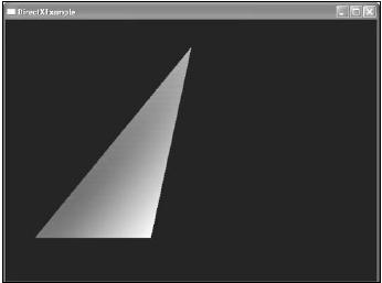 The output of Example 1. Rendering a Scene Before you can render 3D primitives, you must prepare Direct3D to render. The BeginScene function tells Direct3D that rendering is about to take place. Using the BeginScene function, Direct3D makes sure that the rendering surfaces are valid and ready. If the BeginScene function fails, your code should skip making rendering calls. After rendering is done, you need to call the EndScene function. The EndScene function tells Direct3D that you are finished making rendering calls and the scene is ready to be presented to the back buffer. The code that follows confirms the return codes from BeginScene and EndScene.
	HRESULT hr;
	if ( SUCCEEDED( pDevice->BeginScene( ) ) )
	{
		// Render primitives only if the scene
		// starts successfully
		// Close the scene
		hr = pDevice->EndScene( );
		if ( FAILED ( hr ) )
		return hr;
	}
The previous code confirms that the call to BeginScene is successful before allowing rendering to take place using the SUCCEEDED macro around the call. When rendering is complete, you call the EndScene function. The next code sample shows what an example render function might look like.
	/******************************************************************************
	* render
	******************************************************************************/
	void render()
	{
		// Clear the back buffer to black
		pd3dDevice->Clear( 0, NULL, D3DCLEAR_TARGET,
		D3DCOLOR_XRGB(0,0,0), 1.0f, 0 );
		// Tell Direct3D to begin the scene
		pd3dDevice->BeginScene();
		// Draw the contents of the vertex buffer
		// Set the data stream first
		pd3dDevice->SetStreamSource( 0, buffer, 0, sizeof(CUSTOMVERTEX) );
		// Set the Vertex format for the stream next
		pd3dDevice->SetFVF( D3DFVF_CUSTOMVERTEX );
		// Draw the vertices within the buffer using triangle strips
		pd3dDevice->DrawPrimitive( D3DPT_TRIANGLESTRIP, 0, 1 );
		// Tell Direct3D that drawing is complete
		pd3dDevice->EndScene();
		// copies the back buffer to the screen
		pd3dDevice->Present( NULL, NULL, NULL, NULL );
	}
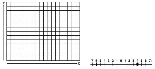
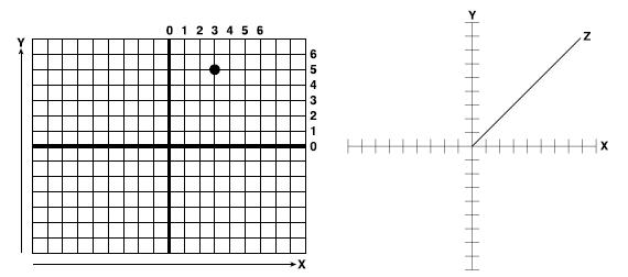
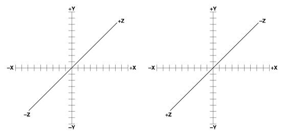
The render function takes all these steps and combines then into a single function. The pd3dDevice variable represents a valid Direct3D device created outside this function. Primitive Types Earlier, you had the option of setting the primitive type that DrawPrimitive would use to render the vertices within the vertex buffer. For the purpose of the previous example, I chose a triangle strip for its speed and ability to add additional triangles easily. This section explains in a little more detail the differences among the available primitive types. Point List A point list consists of a series of points that are not connected in any way. Figure 4.9 shows a grid containing four distinct points. Each point is defined using X, Y, and Z coordinates. For example, the top-left point would be defined as (1, 6, 0). Line List A line list consists of lines constructed by two points, one at each end. The lines within a line list are not connected. Figure 4.10 shows two lines rendered using a line list. This particular line list is constructed from four vertices. The line on the left is formed using (-6, 5, 0) for the upper coordinate and (-4, 2, 0) for the bottom coordinate. Line Strip A line strip is a series of connected lines in which each additional line is defined by a single vertex. Each vertex in the line strip is connected to the previous vertex for a line. Figure 4.11 shows how a line list is constructed and rendered. The line list in this figure is constructed using a series of six vertices, creating five lines. Triangle List A triangle list contains triangles that are not connected in any way and can appear anywhere within your world. Figure 4.12 shows two individual triangles constructed from six vertices. Each triangle requires three vertices to construct a complete triangle. 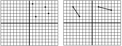 Figure 4.9 An example of rendered points using a point list. Figure 4.10 Lines rendered using a line list.
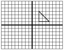
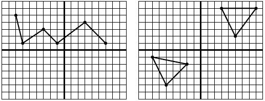 Figure 4.11 Lines rendered using a line strip. Figure 4.12 Triangles rendered using atriangle list. Triangle Strip A triangle strip is a series of triangles connected to one another in which only one vertex is required to define each additional triangle. Figure 4.13 shows four triangles created using only six vertices. Triangle strips are constructed first by creating three vertices to define the first triangle. If an additional vertex is defined, lines are drawn between the two previously created vertices, forming another triangle. In Figure 4.13, the order of the vertices’ creation is shown. 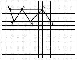 Figure 4.13 Triangles rendered using a triangle strip. Triangle Fan A triangle fan is a series of triangles that share a common vertex. After the first triangle is created, each additional vertex creates another triangle with one of its points being the first vertex defined. Figure 4.14 shows how a triangle fan consisting of three triangles is created using only five vertices. The order of the vertices controls what the triangle fan looks like. Figure 4.14 shows the order of the vertices’ creation needed to construct the displayed fan. 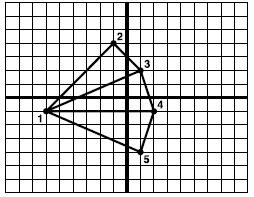 Figure 4.14 Triangles rendered using a triangle fan. |