from http://www.isprs.org/commission5/proceedings06/paper/1255_Dresden06.pdf
BACK TO THE LIBRARY of Sagaidak Darija, DonNTU
ABSTRACT
Camera calibration is a main feature in photogrammetric 3-D object restitution. Calibration parameters such as principal distance, principal point and lens distortion are usually determined by a self-calibrating approach, i.e. they are calculated simultaneously with the object reconstruction by a bundle adjustment based on the collinearity equations and additional correction functions. The adjustment results in the unknown parameters of the interior and exterior orientation and the 3-D object coordinates. The quality of the result depends on several influences, mainly on the image configuration. If the network geometry is not adequate to self-calibration, a priori knowledge about the camera parameters is required, e.g., obtained by testfield calibration. Besides, it can be of interest to transfer the interior orientation parameters determined by a self-calibrating bundle adjustment to another object reconstruction software. This paper reports on the investigation of several bundle programs used to camera calibration. The calibration models are described and the results of self-calibration are discussed.
1. INTRODUCTION
The knowledge of the interior orientation of a camera used for image acquisition is a prerequisite for precise photogrammetric object reconstruction. Parameters such as principal distance, principal point coordinates with reference to the image coordinate system, and some correction terms for lens distortion etc. are determined by camera calibration.
Nowadays, photogrammetric camera calibration is usually carried out together with the calculation of object coordinates within a self-calibrating bundle adjustment. The quality of the result depends on several influences, mainly on the image configuration. If the network geometry is not adequate to selfcalibration requirements, a priori knowledge of the camera parameters is needed for the object reconstruction. In photogrammetry, a series of commercially available programs exists to solve the calibration task. This paper overviews some approaches and discusses the resulting camera parameters. It is not intended to investigate or compare the accuracy of the final 3-D coordinates, computing time or cost, etc. of the different software packages.
The camera calibration test presented in the paper uses real images and real measurement data (chapter 2). This may possibly lead to misinterpretations and incorrect argumentations due to the fact that different results of calibration could be achieved from different real data sets. For further investigations, this disadvantage can be avoided by generating simulated data. But, since simulations do not totally represent the reality of a photogrammetric survey, the simulated data will be derived from an experimental test set-up with optimized image configuration considering all factors existing in practice (chapter 5).
2. TEST SET-UP
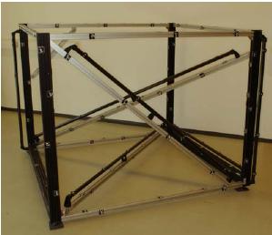
The comparison between different software for camera calibration was performed using a 3-D testfield (Fig. 1) established at AICON 3D Systems, Germany, with reference to the German VDI/VDE guideline 2634. Part 1 of this guideline deals with acceptance and verification methods for optical 3-D measuring systems based on point-by-point probing (VDI/VDE, 2002). The recommended test set-up includes a spatial arrangement of signalized points attached to several measuring lines. Further details concerning the testfield and the acceptance test can be found in VDI/VDE (2002).
Figure 1. Testfield
A Rollei d7 metric5 was used for digital image acquisition. This 5 megapixel camera (2552 x 1920 pixel with approx. 3.5 Ám pixel spacing; Fig. 2) provides some features of a metric camera such as a fixfocus lens (7 mm nominal focal length) and a rigid connection between lens and CCD sensor. The camera geometry can be assumed stable during a series of images (Peipe & Stephani, 2003).
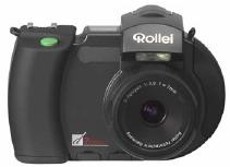
Figure 2. Rollei d7 metric5
60 digital images were taken round about the testfield, including images rotated around the optical axis to allow a precise and reliable determination of the interior orientation parameters of the camera. Automatic image measurement of corresponding points was performed within the AICON DPAPro bundle triangulation software (Aicon, 2006). Subsequent to blunder detection a corrected data set was available for the calibration computation.
The combined calculation of camera parameters and object coordinates in the bundle adjustment is based only on the measurement of corresponding image points (pointcloud calibration). The 3-D point field used does not have to be precisely surveyed.
3. SOFTWARE
The following bundle adjustment and camera self-calibration software has been investigated:
All these commercially available programs enable the determination of the principal distance c, the position of the principal point xo', yo' and radial symmetric and decentering distortion parameters.
4. RESULTS OF CAMERA CALIBRATION
In Tab. 1 the outcome of the camera self-calibration performed with the software I is shown in order to give an impression of the accuracy achieved. The resulting RMSE of the image coordinate observations amount to 0.32 Ám in x-direction and 0.31 Ám in y-direction. The standard deviations of the adjusted object coordinates are Sx=0.050 mm, Sy=0.055 mm and Sz=0.050 mm.
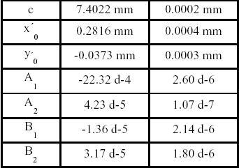
Table 1. Results of camera calibration (software I)
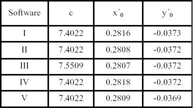
Table 2. Parameters c, and xo', yo'
The comparison of the values of the position of the projection centre in image space is presented in Tab. 2. Very similar results appear for the parameters c, xo', yo', with the exception of program III. The Australis software uses another parameterisation of the radial-symmetric distortion that influences also the value of the principal distance (Gaussian lens distortion; equation (1)).
dr'rad=K1×r'3+K3×r'5+ ... (1)
The other programs apply the balanced form for modeling the radial symmetric distortion (2)
dr'rad=A1×r'(r'2-ro'2)+A2×r'(r'4-ro'4)+ ... (2)
The balanced form has a second zero distortion at a selected radial distance r'o, usually at approximately 2/3 of the maximum of r'. The calculation of the "balanced" principal distance from the results of software III leads to the same value c = 7.4022 mm as for the other programs.
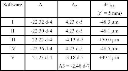
Table 3. Radial symmetric distortion
In Tab. 3 the parameters of the radial symmetric distortion are compared. All values refer to the balanced form (A1, A2) or are converted to, respectively. The resulting numbers are similar, but slightly different. In addition, the distortion values for a radial distance of 5 mm are listed in Tab. 3. Software V applies three radial distortion parameters (A1, A2, A3) instead of only A1, A2. However, the resulting dr' fits well into the other values. The changed signs of the parameters of programs III and V compared to I, II and IV have to be noticed. This stems from expressing them in the sense of a correction or an error.
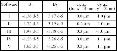
Table 4. Decentering distortion
The comparison of the values of the decentering distortion provides similar, relatively small discrepancies (Tab. 4). The standard equations for the decentering distortion are
dx'dac=B1×(r'2+2x'2)+2B2x'y' (3)
dy'dac=B1×(r'2+2y'1)+2B2x'y' (4)
All the programs utilize these formulas, with the exception of software V. In Phoxy a balanced form of the equations (3) and (4) is used leading to different parameter values, but similar dr'. Again, the change in coefficient signs has to be noticed (software III and V).
In addition to Tab. 4, the influence of the decentering distortion is illustrated with calculated values at five image points being located in the lower right area of the image (Fig. 3; Tab. 5, 6).
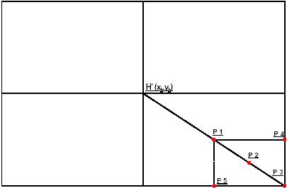
Figure 3. Sensor format of the Rollei camera and array of image points for describing the effect of decentering distortion
Table 5. Decentering distortion in Ám (software I and II)
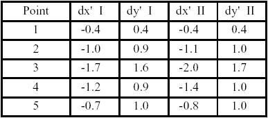
Table 6. Decentering distortion in Ám (software III and IV)
5. CONCLUSIONS AND OUTLOOK
This paper has reported on the comparison of camera parameters determined by self-calibration within several commercial bundle adjustment programs. The calculated interior orientation parameters are more or less suitable to be introduced into photogrammetric object reconstruction software as known values, if it is not possible to compute these data together with the reconstruction process itself, e.g., due to a network geometry not optimal for self-calibration.
The results show a sufficient coincidence of the position of the projection centre in image space (c, xo', yo' ). Small discrepancies appear with the distortion data.
It is aimed to investigate some additional camera calibration programs in the future, such as PhotoModeler, ShapeCapture etc.. As mentioned in chapter 1, simulated data will be generated and used for further tests. But, these simulations should be based on a real, optimised image configuration comprising a lot of converging and rotated digital images and well distributed signalized points (El-Hakim et al., 2003; Hastedt et al., 2005).
6. REFERENCES
Aicon, 2006. Product information DPA-Pro.
www.aicon3d.com (accessed 15 July 2006)
El-Hakim, S.F., Beraldin, J.-A. & F. Blais, 2003. Critical Factors and Configurations for Practical Image-Based 3D Modeling. In: Proceedings "Optical 3-D Measurement Techniques VI" (Eds. A. Gr³n & H. Kahmen), Institute of Geodesy and Photogrammetry, ETH Zurich, pp. 159-167.
Eos Systems, 2006. Product information PhotoModeler.
www.photomodeler.com (accessed 15 July 2006)
Geodelta, 2006. Product information Phoxy.
www.geodelta.com (accessed 15 July 2006)
Hastedt, H., Luhmann, T. & W. Tecklenburg (2005): Simulationsbasiertes Systemdesign f³r die optische Messtechnik nach VDI/VDE 2634. In: Publ. DGPF, Bd. 14 (Ed. E. Seyfert), Potsdam, pp. 319-326.
K2, 2006. Product information CAP.
www.k2-photogrammetry.de (accessed 15 July 2006)
Peipe, J. & M. Stephani, 2003. Untersuchungen zur Stabilitõt und metrischen Qualitõt einer digitalen 5 Megapixel Messkamera. In: Photogrammetrie, Laserscanning, Optische 3DMesstechnik (Ed. T. Luhmann), Wichmann, Heidelberg, pp. 51- 56.
Peipe, J. & W. Tecklenburg, 2006. Vergleich von Softwaretools zur Kamerakalibrierung. In: Photogrammetrie, Laserscanning, Optische 3D-Messtechnik - Oldenburger 3D-Tage 2006 (Eds. T. Luhmann & Ch. M³ller), Wichmann, Heidelberg, pp. 106- 111.
Phocad, 2006. Product information PHIDIAS.
www.phocad.de (accessed 15 July 2006)
Photometrix, 2006. Product information Australis.
www.photometrix.com.au (accessed 15 July 2006)
Remondino, F. & C. Fraser, 2006. Digital Camera Calibration Methods: Considerations and Comparisons. Proceedings ISPRS Commission V Symposium, Dresden, 25.-27. Sept. 2006 (in press).
VDI/VDE, 2002. VDI/VDE Guideline 2634 Part 1, Optical 3D measuring systems û Imaging systems with point-by-point probing. Beuth Verlag, Berlin.