
For today satellite communication channels and broadcasting plays the important role for the person,
society and the state as a whole. Today the satellite TV and the Internet get more and more high rates of growth,
some modern multiservice networks and communication channels are based on satellite receiving. There are lot of
installed satellite dishes for receiving of satellite TV, the Internet, realization of communication, advertising,
etc. almost on each apartment house and establishment. Thus the need of adjustment of satellite antennas increases
every day. Having analyzed a sales’ level of systems for receiving of satellite signal, the number of
installations of satellite dishes makes more than fifty for one day in Donetsk area. Initial data for
adjustment of the satellite antenna are the longitude of the satellite (an orbital position) and geographical
coordinates of an installation location of the antenna. Satellites are in a geostationary orbit above equator,
and angular speed of the satellite is equal to angular speed of our planet, hence, the satellite concerning
in the given location is motionless and the satellite antennal is adjusted only once. Process of adjustment
consists of two stages: rough adjustment and accurate. Rough adjustment is orientation of the antenna on
azimuth and an elevation angle, exact - adjustment of the antenna for receiving of a useful signal by means
of measuring devices (spectrum analyzers and selective micro voltmeters of the MICROWAVE-RANGE).
 Without rough adjustment performance of exact adjustment (antenna’s adjustment directly on receiving of a useful signal)
is practically ineffectual pursuit as the antenna has the narrow antenna diagram which lays within the limits of
1.5-2.5 degrees. To adjust the antenna roughly means, that orientation of the dish regarding an elevation angle
and azimuth should be executed with a margin error, which isn’t exceeding width of the antenna diagram.
Without rough adjustment performance of exact adjustment (antenna’s adjustment directly on receiving of a useful signal)
is practically ineffectual pursuit as the antenna has the narrow antenna diagram which lays within the limits of
1.5-2.5 degrees. To adjust the antenna roughly means, that orientation of the dish regarding an elevation angle
and azimuth should be executed with a margin error, which isn’t exceeding width of the antenna diagram.
Azimuth is an angle between direction on the true North and a direction on the satellite in horizontal plane. Elevation angle is an angle between a horizontal and a direction on the satellite in vertical plane (fig. 1).
The azimuth and elevation angle are functions of following arguments: latitude and a longitude of location, an orbital position of the satellite. Existing methods such as cartography and compass, are inaccurate, have a small level of flexibility for adjustment of the satellite dish. Application of these ways means presence of experience and skills of work for the given location. Conditions for installation of antennas differ at different geographical coordinates on a planet. For example, satellite Telstar12 15W is low above horizon in our location, therefore the offset satellite dishes which have been adjusted on this satellite, look " in the ground " in our location; besides parameters for rough adjustment of the dishes differ from parameters for adjustment, for example, in Kazakhstan. In fact the azimuth and elevation angle for the current satellite depends on latitude and a longitude of location. It can appear as a difficult problem for fitters which have got used to adjust the dish in the same direction. Hence, there is required a device of higher level which should possess following properties:My master’s work is devoted to the first stage satellite antennas adjustment - to definition of elevation angle and azimuth regarding geomagnetic field with high accuracy. An overall objective of research is creation of the device small on dimensions which accuracy allowed to focus the satellite aerial on the set satellite. Definition of parameters of rough adjustment is based on geomagnetic field parameters measurement a and error sources influence indemnification. There are being solved following problems:
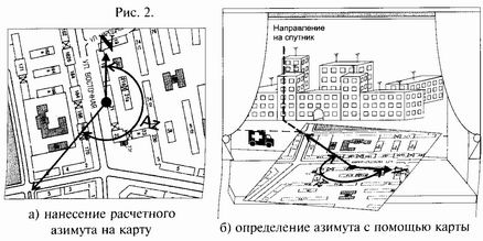
 The first way is the most popular and simple. To align the dish on a calculated azimuth, you should place compass
that the arrow "North" was combined with zero of a scale of azimuths.
The imagined line which is passing through an axis of an arrow and division of a scale,
corresponding a calculated azimuth, will point a direction to the satellite.
The first way is the most popular and simple. To align the dish on a calculated azimuth, you should place compass
that the arrow "North" was combined with zero of a scale of azimuths.
The imagined line which is passing through an axis of an arrow and division of a scale,
corresponding a calculated azimuth, will point a direction to the satellite.
Advantages:
Disadvantages:
More exact way of definition of an azimuth is the cartographical way.
 НIt is necessary to take a map of city or the plan of location,
the electronic variant is possible. Bases of electronic maps of cities can be found in the Internet,
for example, http://maps.yandex.ru. You should label a point on a map which corresponds to
place where installation of the dish is supposed, and by means of a protractor to trace from this point
a calculated azimuth. You should know that on all maps the vertical direction corresponds to the North.(fig. 2a).
Then with this map you should go to installation place and turn map so that directions on a map have coincided with
the same directions on location. Most easier to use a direction of street – you should place map so that the drawn
street was parallel to the wall of the real house leaving on this street.
Now the pencil azimuth on map points exact direction to the satellite (fig. 2b).
НIt is necessary to take a map of city or the plan of location,
the electronic variant is possible. Bases of electronic maps of cities can be found in the Internet,
for example, http://maps.yandex.ru. You should label a point on a map which corresponds to
place where installation of the dish is supposed, and by means of a protractor to trace from this point
a calculated azimuth. You should know that on all maps the vertical direction corresponds to the North.(fig. 2a).
Then with this map you should go to installation place and turn map so that directions on a map have coincided with
the same directions on location. Most easier to use a direction of street – you should place map so that the drawn
street was parallel to the wall of the real house leaving on this street.
Now the pencil azimuth on map points exact direction to the satellite (fig. 2b).
Advantages:
Disadvantages:
It is the big necessity to develop the device which will have minimum disadvantages or they are absent.
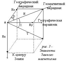
For orientation of the satellite dish, i.e. for definition of an azimuth and elevation angle I suggest to use method of geomagnetic field components measurement with the further processing the measured quantities. In each point of space ( point A on fig. 1) geomagnetic field is characterized by a vector of intensity Т. The quantity and direction of this vector are defined by components Hx, Hy, Hz (northern, east and vertical) in Cartesian system of coordinates or by Geomagnetism’s elements: horizontal intensity H, inclination I and declination D. The intensity of geomagnetic field is a constant with definite tolerance which lays within the limits 15 A/m at magnetic poles to 55 A/m at equator. Magnetic declination is a difference between true north and magnetic north. To determine a heading concerning geomagnetic field, it is necessary to know declination angle. Declination angle is different for different geographical coordinates. There are special maps in which displays declination depending on coordinates.
At first you should calculate the azimuth corresponding to certain orbital position of the satellite at the current latitude and longitude : For example, for Donetsk the azimuth for satellite Sirius with orbital position (a longitude of the satellite) 5E at 48N degrees latitude and 37E degrees longitude makes 220 degrees. It means, that the fitter of the antenna should rotate it slowly around of a vertical support until the number on the indicator will not correspond to a calculated azimuth.
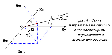
On the other hand, the azimuth for adjustment of the satellite dish is a magnetic azimuth adjusted for declination. Measurement of a magnetic azimuth will be carried out by means of magnetoresistive sensors with sensitivity nearby 0,06 mV/(A/m). Device must have two orthogonal sensors to measure Hx and Hy components (fig. 3-4). If device is in horizontal plane ratio Hy/Hx will be the magnetic north.
If device has a tilt, you should discount it. Z-coordinate discounted too:
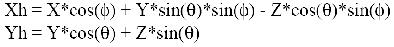
After discounting tilt angles and z-coordinate magnetic azimuth can be calculated:
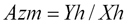
Further amendment of Declination is discounted:
During measuring components of magnetic field and device’s tilt you should discount following error sources:
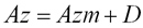
The block diagram of the device is displayed in figure below:
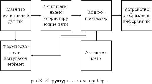 Magnetoresistive sensor consists of permalloy films, which change its resistance on 2-3% depending on applied magnetic
field. Sensor performs transforming field intensity – resistance.
Whitstone bridge with this sensors has its differential output of DC voltage.
Amplifier stage circuits are intended for differential signal amplification with following digitizing.
Magnetoresistive sensor consists of permalloy films, which change its resistance on 2-3% depending on applied magnetic
field. Sensor performs transforming field intensity – resistance.
Whitstone bridge with this sensors has its differential output of DC voltage.
Amplifier stage circuits are intended for differential signal amplification with following digitizing.
Tilt is measured by MEMS (Micro electro mechanical system) – accelerometer. It transforms pitch and roll angles to duty cycle
Microprocessor performs data processing and realizes algorithms for errors compensation with following displaying. The main task of set/reset circuit is restoring sensitivity of magnetoresistive sensors due to disorientation of domains in permalloy films.
The device measures geomagnetic field components, makes data processing and shows orbital position of satellite for current location.