A. Platil1. M. Vopalensky1, P. Ripka1, P. Kaspar1, H. Hauser2
Czech Technical University, Technicka 2,
166 27, Prague 6, Czech Republic, platil@feld.cvut.cz
2TU Wien, Gusshausstrasse 27-29, Wien, Austria
A magnetometer employing the Philips KMZ 51 AMR sensor has been developed. The achieved parameters (using flipping and feedback compensation) comprise linearity error of 0.04 % measured in the +/- 200 A/m range. The temperature coefficient of the sensor sensitivity has been reduced to 0.01 %/K. The temperature coefficient of the sensor offset is about ŢďŇ/Ę. The dependence of the sensor noise and offset stability on the flipping pulse amplitude was measured.
Keywords: magnetic sensors, AMR, magnetometers. Subject category: 4 - Magnetic sensors
In many industrial application areas, the AMR (Anisotropic Magneto-Resistance) sensors [1] are increasingly replacing Hall sensors [2]. Modern AMR sensors (typically in the full Wheatstone - bridge configuration) use barber-pole and flipping techniques to improve their linearity, stability, hysteresis etc. The Philips KMZ51 and KMZ52 [3] sensors have built-in flat flipping and feedback (compensation) coils and thus they are ideally suited for magnetometers.
A simple magnetometer was developed using KMZ51 sensor. The magnetoresistive bridge is supplied from a 3 mA current source so that the temperature coefficient of sensitivity is minimized. The switched-capacitor flipping circuit gives current peaks of up to 2.8 A @ 1 kHz. Thanks to a relatively high current, the sensor is deeply saturated and thus the influence of hysteresis is suppressed and the resistance against field shocks of any direction is improved. The flipping pulse shape was finely tuned using the energetic model applied to magnetization reversal in thin film [4] with respect to heating of the sensor chip.
The bridge output voltage is processed using a preamplifier and a synchronous detector. The controlling pulses (see Fig. 1) driving the synchronous detector are distributed in time in the manner that effectively suppresses the unwelcome transients from flipping [5]. (The post-flip settlement period is ignored and thus the noisiest interval in the signal is not detected.) The timing is controlled by a simple microprocessor.
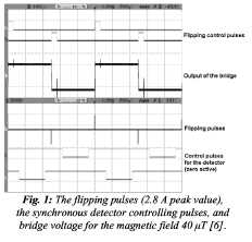
Fig. 1: The flipping pulses (2.8 A peak value), the synchronous detector controlling pulses, and bridge voltage for the magnetic field 40 juT[6].
The hysteresis and linearity error of the sensor (without flipping or compensation) is approximately 0.4% Full Scale (FS ~ +/-200A/m). With the flipping pulses of 2.8 A peak value, the hysteresis is reduced below 0.025 % FS, with the linearity error below 0.2 % FS. An improvement of the instrument range and linearity can be achieved using feedback compensation by the on-chip-integrated coil. In this case, a linearity error of 0.04 % was measured in the +/- 200 A/m range.
The influence of the flipping pulse amplitude on the noise parameters and on the offset stability was measured. The sensor was placed into a six-layer permalloy magnetic shielding, so that the influence of an external magnetic field was minimized. Firstly, the sensor noise has been measured. The sensor was flipped manually (by a single pulse) with decreasing amplitude of the pulse. The noise was measured using Stanford Research SR770 FFT spectrum analyzer. For flipping pulse amplitude of 2.8 A, the noise PSD was 3.2nT/VHz@ 1 Hz.
The noise rms value was about 8.6 nT in lie 100 mHz to 10 Hz frequency range and the noise peak to peak value was about 35nT. For lower values of the flipping current peak, the noise increases as shown in Fig. 2."
It was observed that the offset of the sensor strongly depends on the flipping pube peak value. If die pulse amplitude is not sufficient, the sensor output does not settle to the same value as that before die puke. The variance of settled offset values between flipping pulses decreases with pulse amplitude as shown in Fig. 3 and 4.