|
UNDESTENDING ELECTRIC ARC FUNACE OPERATIONS FOR STEEL PRODUCTION
cmP Techcommentary Vol. 3, No. 2, 1987 published by the Center for Metals Production
An EPRI Sponsored R&D Applications Center
В Internet: http://www.p2pays.org/ref/10/09033.pdf
Introduction
The use of electric arc furnaces (EAF) for steelmaking has grown dramatically in the last decade in the
Untied States. In 1975 electric furnaces accounted for 20% of the steel produced in the U.S.; by 1985 this
figure had grown to 34%. Electric furnaces range in capacity from a few tons to as many as 400 and a
steelmaking shop can have a single furnace or up to three or four. In brief, these furnaces melt steel
by applying an AC current to a steel scrap charge by means of graphite electrodes. It requires about 500 kWh
of electricity to produce a ton of steel; consequently, these furnaces use a tremendous quantity of
etectricity. Transformer loads may reach 120 MVA.
The melting process involves the use of large quantities of energy in a short time (1-2 hr) and in some
instances the process has caused disturbances in power grids. These disturbances have usually been
characterized as "flicker" — brief irregularities in voltage a fraction of the 60 Hz cycle in length,
and "harmonics" — irregularities that tend to occur in a pattern repetitive to the 60 Hz cycle.
The features of electric arc furnaces were described in a CMP Tech-Commentary on Eiectric Arc
Furnaces (Vol. 1, No. 3,1985). The purpose of the present TechCommentary is to give utilities and steel
mills a better understanding of electric furnaces from an electrical viewpoint.
Energy Needs
Furnaces are often classifled by power requirement levels. A scale indicating power classification
ranging from ultra-high-power (UHP), with over 700 kVA per ton, down to low-power, with less than 200 kVA
per ton, is shown in Figure 1 along with some representative furnaces.
It is important to consider the energy
balance for a typical modern EAF The energy diagram shown in Figure 2 indicates that 70% of the totat
energy is etectrical, the remainder being chemical energy arising from the oxidation of elements such
as carbon, iron, and silicon and the burning of natural gas with oxy-fuet burners. About 53% of the
total energy leaves the furnace in the liquid steel, white the remainder is lost to slag, waste gas,
or cooling.
Typical tap-to-tap time has decreased
from over 2 hours in 1960 to 70-80 minutes today. Primarily responsible are UHP furnaces, oxy-fuel
burners, water-cooled side panels (which allow for higher power after the steel is molten), foamy
slag practices (which also permit higher power), and ladle metallurgy (which removes the refining
function from the furnace and shifts it to a ladle into which the molten metal is poured).
KVA
PER
TON
1000 -
900 -
800 -
700 -
600 -
500 -
400 -
300 -
200 -
100 -
|
ULTRA-HIGH
|
EXAMPLES
CHAPARRAL
BETHLEHEM(JOHNSTOWN) |
HIGH
| ISLAND
LUKENS "A"
ATLANTIC STEEL |
MEDIUM
| ARMCO (KANSAS CITY) |
LOW
| LTV (CLEVELAND) |
Figure 1 EAF Power Classifications |
|
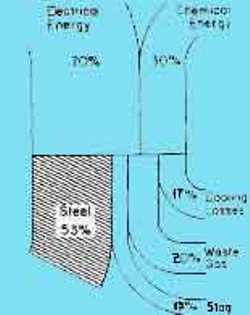
Figure 2 Energy Patterns in an Electric Furnase |
|
Typical Steelmaking Cycle
To achieve meltdown as quickly as possible, etectrodes are initialed towered to a point above the material,
the current is initiated, and the etectrodes bore through the scrap to form a pool of liquid metal. The
scrap itself protects the furnace lining from the high-intensity arc. Subsequently, the arc is lengthened
by increasing the voltage to maximum power. Most modem furnaces are equipped with water-cooled panels in
the upper half of the sidewall, rather than refractories, which allows for longer arcs and higher energy
input into the furnace. In the final stage, when there is a nearly complete metal pool, the arc is
shortened to reduce radiation heat losses and to avoid refractory damage.
After melt down, oxygen usually is injected to
oxidize the carbon in the steel or the charged carbon. This process is an important source of energy;
the carbon monoxide that evolves helps minimize the absorption of nitrogen and flushes hydrogen out of
the metal. It also foams the stag, which helps minimize heat loss.
Detailed Electrical Operation
After an electric furnace is charged with scrap and the roof is in place, the operator lowers the
electrodes, each of which has its own regulator and mechanical drive. The electrodes are connected
to the furnace transformer's secondary delta winding, which may be rated from about 600 to 850 volts.
No current flows when the first etectrode contacts
scrap, but a line-to-line path through the scrap and an arc are established when the second electrode
completes the circuit. The regulators for each of these two electrodes then signal the drives to raise
the etectrodes until the selected current-voltage ratio for the arc is achieved, initiation of the third
arc depends on the scrap's location, which is unpredictabte, hence the duration of the unbalance is short
but random. White the scrap is still unmelted, the arc may easily be extinguished by a minor overshoot in
an electrode regulator or by physical movement of the scrap. As the scrap melts, it can often shift and
fall away from an electrode — extinguishing the arc, or against the electrode — possibly breaking it.
Because of the physical movement and settling of
the scrap, wide excursions can take place on a random basis in the secondary circuit. The abrupt
initiation and interruption of current flow provides a source of harmonic currents and causes
considerable disturbance to high-impedance circuits. (About 75% of the total impedance is in the
secondary circuit.) Voltage and current waves deviate considerably from symmetrical sinusoidal patterns,
but they do not attain full rectangular shape, according to findings in the CMP report, "Arc Furnace
Power Delivery Scoping Study."1 Disturbances are worst during early meltdown, and they occur at varying
frequencies.
|
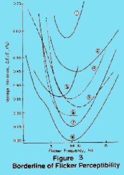
Many attempts have been made to establish the
human eye's reaction to the flicker of a tamp. That these endeavors have not exactly confirmed one
another is shown in Figure 3 (from "Arc Furnace Power Delivery"), where perception is measured white
disturbance voltage and frequency are varied. Eye response to disturbances in the 5-10 Hz range did seem
to be greatest in all the studies.
Generation of harmonics may result in further
flicker problems, and equipment on the power system may also be damaged. If static capacitors are to
be used to improve the power factor, an analysis to ensure that resonance does not exist at any of the
harmonic frequencies should be made. Harmonics contribute to wave distortion and to the increase in
effective inductive reactance. This increase is often in the 10 to 15% range and has been reported as
high as 25%. Current into the furnace is therefore less than what would be expected from calculations
based on sinusoidal wave shapes, and tosses in frequency-sensitive equipment such as transformers are
higher than the sinusoidal wave shape would produce.
|
Reducing Electrical Disturbances
Many ways exist to reduce the effects of the arc disturbances. These are determined by the utility
system to which the furnace or furnaces are to be connected, and they are influenced mainly by the
size and stability of the power grid. Some sizable shops require no particular flicker control equipment.
It is quite possible that, if a furnace shop is fed from a 220 kV or higher system with a short-circuit
capacity of 6500 MVA or more, the utility will experience very little toad disturbance, and the steelmaker
can have considerable flexibility in configuring his internal plant power system.
Most utilities require power factor
correction. Shops with large electric furnaces would more than likely use static capacitors; synchronous
condensers of sufficient capacity would be prohibitively expensive for a multifurnace shop. Before such
systems are instated, transient analysis is required to determine:
(a) Capacitor bank configuration
(b) Need for harmonic tuning of sections
(c) Switching procedure (This is important to avoid a power factor penalty
and does not eliminate flicker.)
If additional regulation is needed,
VAR control equipment would probably be required. However, if plans have already been made for power
factor capacitors, including tuning reactors, then the thyristors and main reactor are the only further
additions required.
Utility Engineering Progress
Most of the larger electric arc furnaces installed over the past 20 years have been fed from high-voltage,
stiff utility power grids. Problems of previous years — transformers fatting because of resonance on a
certain tap combination or utility capacitor banks failing far from an offending furnace — have not been
repeated. Users and utilities have done their homework prior to installation, and potential problems have
been identified and corrected. The user can decide what to do inside his plant regarding the potential
flicker problem. For example. he may want to install harmonic filters, which would also help, avoid power
factor penalties. It is also helpful that makers of electronic apparatus - computers, TV, X ray, etc.—have
improved their power supplies in recent years, making these systems less vulnerabte to power ftuctuations.
Most important, utilities have become
vitally interested in power quality. To further this goal, the Electric Power Research institute has
formed a Power Electronics Applications Center to investigate further the question of utility power
quality.
Bibliography
1. "Arc Furnace Power Delivery Scoping Study," Center for Metals roduction,
Report No. 84-1,1984.
2. "Arc Stability in Electric Furnace Steelmaking," Center for Metals Production, Report No. 86-9,1986.
3. W. E. Schwabe. "Experiment^ Results with Hollow Electrodes," Iron and Steel Engineer, June 1957, pp. 84-92.
4. W. J. Maddever. "Gas Injection Process During Electric Furnace Steelmaking and Continuous Casting," Ph.D. thesis, University of Toronto, 1978.
5. "DC Arc Furnaces for Steel Production. Center for Metals Production, Report No. 86-8,1986.
6 "Techno-Economic Assessment of Electric Steelmaking Through the Year 2000 EPRI, 1987 (to be published).
CMP Publications of interest
84-1 Arc Furnace Power Delivery (1984)
A detailed analysis of the technical problems relating to large electric furnaces and utility power grids.
85-1 Ladle Refining Furnaces for the Steel Industry (1985)
A review of supplemental steel heating and refining units often used in conjunction with electric arc furnaces.
85-2 Electric Arc Furnace Dust Disposal (1985)
An analysis of dusts generated by electric furnaces and a review of methods for treatment and disposal.
Vol. 1, No. 3 Electric Arc Furnace Steelmaking (TechCommentary -1985) A description o! the structure and function of electric arc furnaces
86-7 Electrode Tip Analysis (1986)
An examination of electrode wear by various photographic means
86-8 DC Arc Furnaces for Steel Production (1986)
A comparison of the electrical energy consumption of a conventional 30 ton AC furnace with a 30 ton DC furnace.
86-9 Arc Stability in Electric Furnace Steelmaking (1986)
Field testing the effect on furnace performance of hollow electrodes, lime and argon injection, and changes in other operating parameters.
|