CAPACITOR
The free encyclopedia Wikipedia
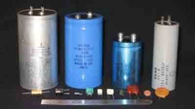
Capacitor
A capacitor is an electrical/electronic device that can store energy in the electric field between a pair of conductors (called "plates"). The process of storing energy in the capacitor is known as "charging", and involves electric charges of equal magnitude, but opposite polarity, building up on each plate.
Capacitors are often used in electric and electronic circuits as energy-storage devices. They can also be used to differentiate between high-frequency and low-frequency signals. This property makes them useful in electronic filters.
A capacitor consists of two conductive electrodes, or plates, separated by a dielectric.

Capacitance
The capacitor's capacitance (C) is a measure of the amount of charge (Q) stored on each plate for a given potential difference or voltage (V) which appears between the plates:
Ń = Q / V
In SI units, a capacitor has a capacitance of one farad when one coulomb of charge is stored due to one volt applied potential difference across the plates. Since the farad is a very large unit, values of capacitors are usually expressed in microfarads (µF), nanofarads (nF), or picofarads (pF).
Óęŕçŕííűĺ çŕäŕ÷č äîëćíű đĺřŕňüń˙ ęŕę íŕ ńňŕäčč ďđîĺęňčđîâŕíč˙ č đĺęîíńňđóęöčč ŃÝŃ, ňŕę č íŕ ýňŕďĺ ýęńďëóŕňŕöčč.
When there is a difference in electric charge between the plates, an electric field is created in the region between the plates that is proportional to the amount of charge that has been moved from one plate to the other. This electric field creates a potential difference V = E•d between the plates of this simple parallel-plate capacitor.
The capacitance is proportional to the surface area of the conducting plate and inversely proportional to the distance between the plates. It is also proportional to the permittivity of the dielectric (that is, non-conducting) substance that separates the plates.
The capacitance of a parallel-plate capacitor is given by:

where Ĺ - is the permittivity of the dielectric,
A - is the area of the plates,
D - is the spacing between them.
Impedance
The ratio of the phasor voltage across a circuit element to the phasor current through that element is called the impedance Z. For a capacitor, the impedance is given by:

where  - is the capacitive reactance, - is the capacitive reactance,
 - is the angular frequency, - is the angular frequency,
f - is the frequency,
C - is the capacitance in farads,
j - is the imaginary unit.
Hence, capacitive reactance is the negative imaginary component of impedance. The negative sign indicates that the current leads the voltage by 90° for a sinusoidal signal, as opposed to the inductor, where the current lags the voltage by 90°.
Reactance is so called because the capacitor doesn't dissipate power, but merely stores energy. In electrical circuits, as in mechanics, there are two types of load, resistive and reactive. Resistive loads dissipate the energy delivered by the circuit as heat, while reactive loads store this energy, ultimately delivering the energy back to the circuit.
Also significant is that the impedance is inversely proportional to the capacitance, unlike resistors and inductors for which impedances are linearly proportional to resistance and inductance respectively. This is why the series and shunt impedance formulae are the inverse of the resistive case. In series, impedances sum. In parallel, conductances sum.
Capacitors in a parallel configuration each have the same potential difference (voltage). Their total capacitance (Ceq) is given by:


The reason for putting capacitors in parallel is to increase the total amount of charge stored. In other words, increasing the capacitance also increases the amount of energy that can be stored. Its expression is:

The current through capacitors in series stays the same, but the voltage across each capacitor can be different. The sum of the potential differences (voltage) is equal to the total voltage. Their total capacitance is given by:


Capacitor types
By dielectric material
Vacuum : Two metal, usually copper, electrodes are separated by a vacuum. The insulating envelope is usually glass or ceramic. Typically of low capacitance - 10 - 1000 pF and high voltage, up to tens of kilovolts, they are most often used in radio transmitters and other high voltage power devices. Both fixed and variable types are available. Vacuum is the most perfect of dielectrics with a zero loss tangent. This allows very high powers to be transmitted without significant loss and consequent heating.
Air :Air dielectric capacitors consist of metal plates separated by an air gap. The metal plates, of which there may be many interleaved, are most often made of aluminium or silver-plated brass. Nearly all air dielectric capacitors are variable and are used in radio tuning circuits..
Plastic film: Made from high quality polymer film (usually polycarbonate, polystyrene, polypropylene, polyester and for high quality capacitors polysulfone), and metal foil or a layer of metal. They have good quality and stability, and are suitable for timer circuits. Their inductance limits use at high frequencies.
Mica: Similar to glass. Often high voltage. Suitable for high frequencies. Expensive. Excellent tolerance & stability.
Paper: Used for relatively high voltages. Known for long term failures.
Glass: Used for high voltages. Expensive. Stable temperature coefficient in a wide range of temperatures.
Ceramic: Chips of alternating layers of metal and ceramic, or disks of ceramic with metal on both sides of the disk. The dielectrics are broadly categorized as Class 1 or Class 2. Class 2 ceramic capacitors have strong variation of capacitance, high dissipation factor, high frequency coefficient of dissipation, and their capacitance depends on applied voltage and changes with aging. However they find massive use in common low-precision coupling and filtering applications. Suitable for high frequencies.
Aluminum electrolytic: Polarized. One electrode made of aluminum foil, (etched aluminium to acquire much larger surface area. The dielectric is oxide grown on the etched aluminum plate,) and the second electrode is a liquid electrolyte. Bad frequency characteristics make them unsuited for high-frequency applications.
Tantalum electrolytic: Similar to the aluminum electrolytic capacitor but with better frequency and temperature characteristics. High dielectric absorption and high leakage [4]. Although they share many of the disadvantages of aluminum electrolytics, they perform better on most attributes; for example, they have much better performance at low temperatures.
AC capacitors are capacitors specifically designed to work on line (mains) voltage ac power circuits. These are commonly used electric motor circuits. They are often designed to handle large currents so they tend to be physically large. They are usually ruggedly packaged, often in metal cases that can be easily grounded/earthed. They also tend to have rather high DC breakdown voltages.
|