HYDRAULIC MACHINERY
From Wikipedia, the free encyclopedia.
Hydraulic machinery are machines and tools which use fluid power to do work. Heavy equipment is a common example.
In this type of machine, high pressure hydraulic fluid is transmitted throughout the machine to various hydraulic motors and hydraulic cylinders. The fluid is controlled directly or automatically by control valves and distributed through hoses and tubes.
The popularity of hydraulic machinery is due to the very large amount of power that can be transferred through small tubes and flexible hoses, and the high power density and wide array of actuators that can make use of this power.
Force multiplication
An interesting aspect of hydraulic systems is the ability to apply force multiplication. Imagine if cylinder one (C1) is one inch in diameter, and cylinder two (C2) is ten inches in diameter. If the force exerted on C1 is 10 lbf, the force exerted by C2 is 1000 lbf because C2 is a hundred times larger in area ( ) as C1. The downside to this is that you have to move C1 a hundred inches to move C2 one inch. ) as C1. The downside to this is that you have to move C1 a hundred inches to move C2 one inch.
Hydraulic circuits

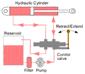
A simple open center hydraulic circuit |

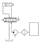
The equivalent circuit schematic |
For the hydraulic fluid to do work, it must flow to the actuator and or motors, then return to a reservoir. The fluid is then filtered and re-pumped. The path taken by hydraulic fluid is called a hydraulic circuit of which there are several types. Open center circuits use pumps which supply a continuous flow. The flow is returned to tank through the control valve's open center; that is, when the control valve is centered, it provides an open return path to tank and the fluid is not pumped to a high pressure. Otherwise, if the control valve is actuated it routes fluid to and from an actuator and tank. The fluid's pressure will rise to meet any resistance, since the pump has a constant output. If the pressure rises too high, fluid returns to tank through a pressure relief valve. This type of circuit can use inexpensive, constant displacement pumps.
Closed center circuits supply full pressure to the control valves, whether any valves are actuated or not. The pumps vary their flow rate, pumping very little hydraulic fluid until the operator actuates a valve. The valve's spool therefore doesn't need an open center return path to tank. Multiple valves can be connected in a parallel arrangement and system pressure is equal for all valves.
A Hydraulic cylinder (also called a linear hydraulic motor) is a mechanical actuator that is used to give a linear force through a linear stroke. It has many applications, notably in engineering vehicles.
Operation
Hydraulic cylinders get their power from pressurized hydraulic fluid, which is typically oil. The cylinder consists of a cylinder barrel, in which a piston connected to a piston rod is moving. The barrel is closed by the cylinder bottom and by the cylinder head where the piston rod comes out of the cylinder. The piston has sliding rings and seals. The piston divides the inside of the cylinder in two chambers, the bottom chamber and the piston rod side chamber. The hydraulic pressure acts on the piston to do linear work.
A hydraulic cylinder is the actuator or "motor" side of this system. The "generator" side of the hydraulic system is the hydraulic pump, that brings a fixed or regulated flow of oil into the system. Mounting brackets or clevisses are mounted to the cylinder bottom as well as the piston rod.
By pumping hydraulic oil to the bottom side of the hydraulic cylinder, the piston rod starts moving upward. The piston pushes the oil in the other chamber back to the reservoir. If we assume that the oil pressure in the piston rod chamber is zero, the force on the piston rod equals the pressure in the cylinder times the piston area. If the oil is pumped into the piston rod side chamber and the oil from the piston area flows back to the reservoir without pressure, the pressure in the piston rod area chamber is Pull Force/(piston area - piston rod area). In this way the hydraulic cylinder can both push and pull.
Parts of a hydraulic cylinder
A hydraulic cylinder consists out of following parts:
Cylinder barrel
The cylinder barrel is mostly a seamless thick walled forged pipe that must be machined internally. The cylinder barrel is ground and/or honed internally.
Cylinder bottom
In most hydraulic cylinders, the barrel and the bottom are welded together. This can damage the inside of the barrel. Therefore it is better to have a screwed or flanged connection. In that case also the barrelpipe can be maintained and/or repaired in future.
Cylinder head
The cylinder head is sometimes connected to the barrel with a sort of a simple lock (for simple cylinders). In general however the connection is screwed or flanged. Flange connections are the best, but also the most expensive. A flange has to be welded to the pipe before machining. The advantage is that the connection is bolted and always simple to remove. For larger cylinder sizes, the disconnection of a screw with a diameter of 300 to 600 mm is a big problem as well as the alignment during mounting.
Other parts
Piston
Cylinder bottom connection
Piston rod connection
(sometimes) Feet for mounting of the barrel
A hydraulic cylinder should be used for pushing and pulling and no bending moments should be transmitted to the cylinder. For this reason the ideal connection of a hydraulic cylinder is a single clevis with a ball bearing.
Piston Rod construction
The piston rod of a hydraulic cylinder operates both inside and outside the barrel, and consequently both in and out of the hydraulic fluid and surrounding atmosphere.
Metallic coatings
Smooth and hard surfaces are desirable on the outer diameter of the piston rod and slide rings for proper sealing. Corrosion resistance is also advantageous. A chromium layer may often be applied on the outer surfaces of these parts. However, chromium layers may be porous, thereby attracting moisture and eventually causing oxidation. In harsh marine environments, the steel is often treated with both a nickel layer and a chromium layer. Often 40 to 150 micrometer thick layers are applied. Sometimes solid stainless steel rods are used. High quality stainless steel such as AISI 316 may be used for low stress applications. Other stainless steels such as AISI 431 may also be used where there are higher stresses, but lower corrosion concerns.
Первоисточник
|
 ) as C1. The downside to this is that you have to move C1 a hundred inches to move C2 one inch.
