At present, the world's practice to set up dynamic loads on the rock cutting tool is to use vibrators and vibrohammers. However, existing vibrators and vibrohammers cannot be used as downhole devices. Because of this, they are used in drilling short holes with diameters larger than 250 mm. The studies conducted at the Exploration Engineering Chair of Tomsk Polytechnic Institute have shown that vibratory-rotary drilling offers a 2-3-fold increase in penetration speed. With a magnetostriction vibrator, the cutting speed of vibratory-rotary roller-bit drilling is 3.2 to 4.3 times as high as that of rotary drilling. The published results on rock cutting tool wear show that in vibratory-rotary drilling the first-sharpening bit life is 5 to 8 times longer in comparison with rotary drilling. However, magnetostriction sonic borers can be used to the best advantage only in drilling holes with diameters of 250-300 mm and larger. This is due, among other things, to their large overall dimensions. Besides, such vibrators call for electric power supply through the whole depth of the hole. Thus at present it is impossible do drill deep holes with diameters smaller than 250 mm using vibratory drilling.
Over a period of years, self-oscillation regimes in hydraulic systems with cavitating devices have been studied at the Institute of Technical Mechanics (ITM) of the National Academy of Sciences of Ukraine and the National Space Agency of Ukraine under the direction of Prof. Victor V. Pilipenko, Academician of the National Academy of Sciences of Ukraine.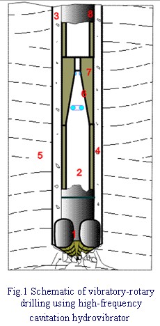
Based on the results of the study of cavity flows in hydraulic systems with different restrictors, a high-frequency cavitation hydrovibrator of radically new design without any moving or rotating parts has been proposed (see its schematic diagram in Fig.1). The cavitation hydrovibrator 7 imparts high-frequency longitudinal vibration accelerations to the rock cutting tool 1 using part of the stream energy of the drilling mud 2 pumped to the borehole 3 to evacuate the cuttings 4 of the rock 5. The hydrovibrator 7 is a part of the drilling assembly 8, and its specially shaped inner passage 6 provides the regime of periodically detached cavitation in the drilling mud flow. The hydrovibrator can be mounted immediately ahead of the rock cutting tool 1 or some distance therefrom (for example, over the core barrel), and it transforms the steady drilling mud flow into a pulsating flow. Part of the pulsatory energy of the drilling mud will be transferred to the drilling assembly structure 8 between the hydrovibrator and the rock cutting tool. This gives rise to the longitudinal vibrations of the rock cutting tool.
In the specially shaped passage 6 of the hydrovibrator 7, the periodic process of growth and detachment of cavities 9 occurs. As soon as the cavity 9 reaches its maximum size that is governed by the flow regime, its diffuser part detaches. The detached part 10 of the cavity 9 is carried downstream and collapses in the pressure zone. When the detached part 10 of the cavity 9 whose volume is comparatively large collapses, an anomalously high pressure is produced in the drilling mud flow. The pressure wave from the collapse center runs downstream to a distance as long as several meters with little or no damping, while the pressure wave that runs upstream is suppressed by the new cavity 9 that has grown by that time as evidenced by the absence of pressure pulsation at the hydrovibrator inlet. However, the backward wave is involved in initiating backward flows and contributes to the detachment of the next cavity. Thus the self-regulated periodic process of cavity detachment and collapse is set up in the flow passage of the hydrovibrator.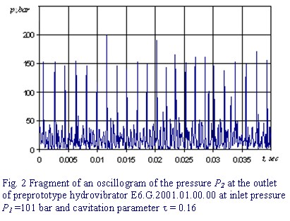
As an illustration, Fig.2 shows a hydrovibrator outlet pressure oscillogram. As the hole depth is increased, the regime of periodically detached cavitation is kept by keeping the requisite pressure at the hydrovibrator inlet. Because the drilling mud pressure oscillations generated in the regime of periodically detached cavitation do not run upstream, the hydraulic system of the mud pump will not be subjected to any dynamic loads. Thus the proposed hydrovibrator is expected to avoid the disadvantages typical of existing hydraulic hammers and vibrators.