Назад в библиотеку
«Dynamic design of automotive systems: Engine mounts and structural joints»
Department of Mechanical Engineering, Ohio State University, Columbus, OH 43210, USA e-mail: singh.3@osu.edu
Abstract. Dynamic design and vibro-acoustic modelling issues for automotive structures are illustrated via two case studies. The first case examines the role and performance of passive and adaptive hydraulic engine mounts. In the second, the importance of welded joints and adhesives in vehicle bodies and chassis structures is highlighted via generic «T» and «L» beam assemblies. In each case, analytical and experimental results are presented. Unresolved re¬search issues are briefly discussed.
Keywords. Dynamic design; engine mounts; structure joints; automotive systems; vibro-acoustic modelling.
1. Introduction
An automotive engine-body-chassis system is typically subjected to unbalanced engine forces, uneven firing forces especially at the idling speeds, dynamic excitations from gearboxes and accessories, and road excitation. Since design trends have been towards compact and efficient automobiles, engine-to-frame weight ratio and engine force densities have increased. Consequently, recent research and development efforts have been focused on improving engine mounting technology to achieve better vibration isolation, smooth vehicle movement, and noise reduction. Such dynamic design issues are illustrated via the hydraulic engine mount case study. Results of mathematical models and experimental studies are presented, and limitations of the passive device are briefly discussed. A new adaptive engine mounting system is proposed, and comparative results are briefly examined.
The dynamic behaviour of welded joints, mechanical fasteners and adhesives in thin sheet automotive structures is poorly understood since engineering design data such as bending or torsional stiffnesses and damping loss factors are virtually nonexistent. Consequently, current design practice is largely empirical, based mostly on the designer's experience and intuition. Design requirements for static and dynamic loadings may conflict, as low stresses in joints demand rigid connections, while designs for low vibration and noise often require more compliant joints. In practice, however, no analytical design tools are available to resolve such issues. While finite element (FEM) solutions are useful if properly implemented, a separate problem-specific solution must be constructed for each joint/structure problem considered. A more general set of analysis tools and design dynamics is required to understand existing designs better and to develop alternate joints based on new or improved welding processes. A problem is formulated in this article with «T» and «L» beam assemblies as generic examples. Procedures for determining joint stiffness are discussed.
2. Case study A: Hydraulic engine mounts
2.1 Passive mount concept.
An engine mount must satisfy two essential but conflicting criteria. First, it should be stiff and highly damped to control the idle shake and engine mounting resonance over 5-30 Hz. Also, it must be able to control, like a shock absorber, the motion resulting from quasi-static load conditions such as travel on bumpy roads, abrupt vehicle acceleration or deceleration, and braking and cornering. Second, for a small amplitude excitation over the higher frequency range, a compliant but lightly damped mount is required for vibration isolation and acoustic comfort, like a conventional rubber mount. A conventional rubber mount cannot satisfy both requirements simultaneously as the lumped stiffness kr and the viscous damping coefficient br in the shear mode are nearly invariant with excitation amplitude and frequency over the concerned excitation range (say 1-250 Hz) of vehicle systems. Thus, a compromise between resonance control and isolation is inevitably needed. The mount is typically optimized for placement, orientation, kr and br. To meet both performance requirements, hydro-mechanical mounts have been designed recently and employed in many vehicles. Figure 1 shows a schematic representation. Such a mount can provide improved stiffness and damping characteristics which vary with frequency and excitation amplitude. It is conceptually the best passive engine mount known at present.
2.2 Mathematical models of passive mount.
Typical dynamic properties are illustrated in figure 2 where K is the dynamic stiffness magnitude, fa is the loss angle and X is the displacement amplitude. Analytical predictions are also compared in this figure based on a nonlinear model that is described in several articles (Singh et al 1992; Kim & Singh 1993, 1995). Excellent agreement between theory and experiment is seen up to 50 Hz.
Figure 3 shows a conceptual quarter-car model that includes the nonlinear mounts and linear suspension system. Here kr and br are frequency variant stiffness and damping coefficients of the top rubber element (in shear mode), me and ms are engine mass and vehicle mass respectively, and u(ω,х) is the time-varying nonlinear hydraulic reaction force. Figure 4 compares the sprung mass acceleration amplitude X"S(ω) spectra for the rubber mount and hydraulic mounts with decoupler gap Δd = 0, 0.7 and 1.4 mm. A high resonant peak occurs at 9.2 Hz for the low damping rubber mount. The inertia track hydraulic mount with Δd = 0 clearly shows its superior dynamic performance up to 15 Hz. Nonlinear effects are seen for Δd = 0.7 and 1.4 mm when both inertia track and decoupler mechanisms are employed. Limitations of the inertia track mount may be seen beyond 15 Hz since it yields high mount stiffness vibration and higher transmissibility.
Dynamic design of automotive systems
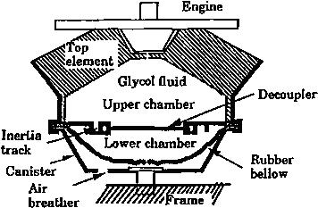
Figure 1. Hydraulic engine mount (passive design).
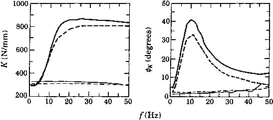
Figure 2. Typical dynamic characteristics of hydraulic mount. Predicted and measured dynamic stiffness spectra of the regular mount. ( Theory for X= 1.0 mm: X = 0.1mm: — experiment for X = 0.1mm; experiment for X = 1.0 mm.)
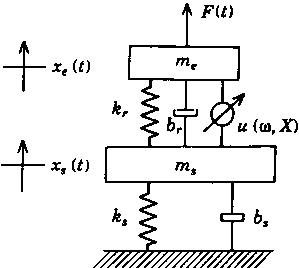
Pigure 3. Quarter-car model with nonlinear hydraulic mount.
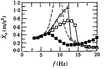
Figure 4. Comparison of rubber and hydraulic mounts using quarter-car model. Simulated harmonic responses of the vehicle model for Fa = 100 N. (Effect of decoupler gap on X"s(ω); , Δd = 0mm: Δ, Δd = 0.7mm: Δ, Ad = 1.4 mm: - - - - rubber mount.)
One may indeed prefer a rubber mount at higher frequencies. Further information on nonlinear models of hydraulic mounts and vibratory power flow concepts may be found in the literature (Singh et al 1992; Kim & Singh 1993, 1995, Roystan & Singh 1995-1997).
Назад в библиотеку