 |
|  ||
DonNTU >
Master's portal
||
DonNTU >
Master's portal
 |
Anatoliy BoyevFaculty: ElectrotechnicalSpeciality: Electrotechnical systems of electroconsumptionTheme of master’s work:Determination of switched reluctance motor characteristics on the basis of magnetic field analysisSuperviser: Leonid Vasiliev |
Biography |
Abstract of master's workAchievements in the field of electric machines, development of semiconductor and computing machinery have predetermined appearance of switched reluctance motors (SRM). Area of SRM application in controlled-velocity electric drive is gradually extends together with synchronous and asynchronous machines. Heightened interest in controlled-velocity electric drive as a whole explained not only by growing technological processes requirements. Questions connected with energy conservation also get the increasing actuality. Effective solution of these problems in most cases becomes possible only on condition of controlled-velocity electric drive using. There is a replacement of the electric drive on the basis of a direct current commutator machines and gradually increasing demand for the contactless controlled-velocity electric drives for today. Serial asynchronous motors are usually used in controlled-velocity electric drive. However some questions coupled with efficiency decreasing and necessity of overestimating of the asynchronous motors installed capacity in the frequency-controlled drive puts a new design and theoretical problems before researchers in this area. In this regard using of electric drive on the basis of SRM can be observed as an alternative to the frequency-controlled electric drive. SRM operation based on the reluctance principle. Electromechanical converter (EC) of SRM has salient pole construction of stator and rotor from laminated steel. Concentrated phase windings are placed on the stator poles. Rotor has no winding. The torque in SRM is produced by consecutive switching cycles of the phases. In each cycle rotor attracted toward the position, which corresponds to the minimum reluctance of motor magnetic system to the magnetic flux of the energized phase. Magnetic field energy is maximum and air gap is minimum in this position (Fig. 1).  Fig. 1. SRM principle of operation (animation: 8 frames, 8 repeat cycles, 104 Kb) Rotor position sensor (RPS), power electronic converter (PEC) and control electronics (CE) are important for the operation of SRM (Fig. 2). 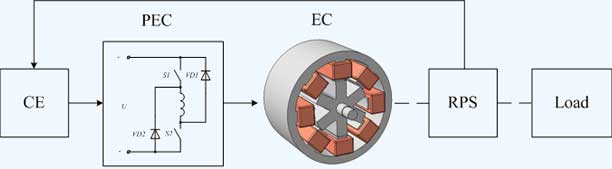 Fig. 2. SRM structure Mathematical modeling is widely applied for researching of SRM characteristics. There are two main approaches to definition and description of magnetic system characteristics. In the context of the first approach analysis of equivalent circuits of motor magnetic system is used. This approach is usually based on the assumption of uniform distribution of induction on the cross-section of different parts of magnetic system. Therefore it does not allow to get a high precision results because it does not take into account local saturation of the pole zone. The second approach is rather perspective. It is grounded on the computation of SRM magnetic system characteristics with the finite element method (FEM). Mathematical description of magnetic system characteristics also plays rather important role. In this respect it is possible to mark out two directions. In the context of the first one procedure of spline interpolation is used. Main disadvantage of this approach consists in limitation on analytical analysis using for energy conversion processes in SRM. Within the limits of the second direction analytical description of the characteristics is used. Power rating of investigated SRM is 130 W. Set of permeance curves was obtained using two-dimensional finite element analysis. Set of curves showed in Fig. 3 as a surface. This surface shows changing of permeance as a two-variable function of phase current and rotor position. 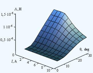 Fig. 3. Magnetic system permeance surface for SRM (these results were obtained using FEA software FEMM [1]) Expression based on cosine permeance change versus rotor position used for approximation of these functional dependences: 
where Λmax(i) - magnetic system permeance dependence versus current for the aligned position of stator and rotor poles; 
where Ψ1, I1 - flux linkage and current in coupling point of linear and nonlinear part of approximated magnetization curve for the aligned position of stator and rotor poles;  Electromagnetic torque curves for investigated SRM is shown in Fig. 4. Torque curves calculated with the expression (1) showed with solid lines. Electromagnetic torque calculated by weighted stress tensor in FEMM showed with dash line. 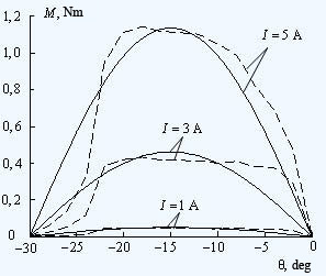 Fig. 4. Static curves showing electromagnetic torque versus rotor position for a set of currents As indicated in the Fig. 4. approximation precision decreases near the aligned and unaligned rotor positions. It can be explained by difference between real permeance curve and cosine function. Expression (1) allows to calculate static electromagnetic torque of SRM. It can be used for electromagnetic process optimization per switching cycle. It is planned to make an analysis of SRM characteristics taking into account local saturation of the pole zone in master’s work.
Note: Master’s work has not finished yet. Full text of work and materials can be received from the author or his supervisor after December, 2009. |