Источник: http://publik.tuwien.ac.at/files/pub-mb_4370.pdf
A DC servo drive with battery power supply, PWM input voltage, and a microcontroller with low sampling rate compared to the drive dynamics is utilized for position control. Motor angle, speed, and current are measured. Load torque, friction and motor parameters are uncertain. A controller should achieve acceptable accuracy even with critical parameter combinations. Therefore, a detailed model capable of reproducing voltages and currents as well as a correct position is formulated. Several linear and non-linear control concepts are investigated by simulation. Due to the hardware limitations which can be found in many embedded systems the linear state regulator proves to be superior to SMC.
The system is modeled in two main sections: 1,The controlled bridge circuit for PWM-generation with 4 transistors including free-wheeling diodes and measuring resistors. 2,The DC drive with electrical resistance, inductance, electromotive voltage, and its moment of inertia. For the freewheeling diodes an exponential characteristic is assumed while all other elements are described by linear relations. The main problem is the switching nature of the input voltage, hence, several cases have to be distinguished [1]:
PWM signal is high: In this case the diodes will be locked and the system behaviour is linear.
PWM signal is low: The system is cut off the power supply in this case and energy is stored in the mass inertia and inductance of the drive. Two sub-cases have to be considered:
Input voltage is negative. The motor current runs through a diode and decreases monotonically.
Input voltage is positive. All diodes are locked but a small current runs through the measuring resistors, therefore providing a means for speed measurement.
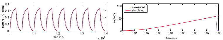
It is critical to properly hand over the system states between the consecutive switched cases. Validation results confirm the excellent model performance (fig.1).
The state-feedback regulator employs angle, spped, current, and integrated position error as states. The limited supply voltage requires the use of limited integrators.
The cascaded controller consists of an inner loop using a classical PI-regulator for speed control, nested into an outer loop with a P-regulator for position.
Two SMC schemes are implemented: One using only output-feedback [2], the other utilizing an additional current-regulator [3]. All controllers are designed for a dominant pair of poles.
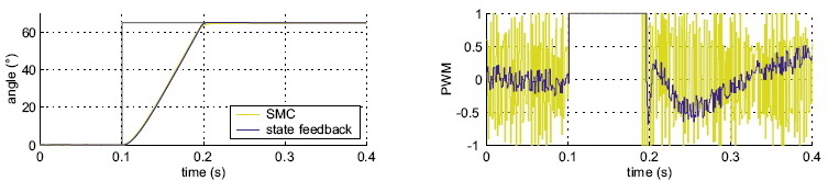
Simulation results clearly show that under the given restrictions the linear controllers perform better than the SMC schemes. In fig.2 the step response of both schemes is nearly identical due to the saturated control variable (worst case of parameter variations plus noise). However, the linear controller shows a much smaller control action resulting in less energy consumption. Additional simulations not shown here reveal that this unfavourable control chattering may be strongly reducing using higher sampling frequencies [1].
A comprehensive, detailed, and accurate model of a DC servo drive has been established and validated. Several control schemes have been tested in simulation for robustness and the linear state-feedback regulator proves to be superior to SMC-schemes because of severe restrictions (common to many embedded systems), namely: 1,Limited supply voltage 2,PWM input variable 3,Comparatively low sampling rate.