Literature: W.Bolton, Mechatronics: Electronic Control Systems in Mechanical and Electrical Engineering (Paperback). - London: 2003. 592p.
A programmable logic controller (PLC) is a digital electronic device (Fig. 1) that uses a programmable memory to store instructions and to implement functions such as logic, sequencing, timing, counting and arithmetic in order to control machines and processes and has been specifically designed to make programming easy. The term logic is used because the programming is primarily concerned with implementing logic and switching operations. Inputs devices, e.g. switches, and output devices, e.g. motors, being controlled are connected to the PLC and then the controller monitors the inputs and outputs according to the program stored in the PLC by the operator and so controls the machine or process. Originally they were designed as a replacement for hard-wired relay and timer logic control systems. PLCs have the great advantage that it is possible to modify a control system without having to rewire the connections to the input and output devices, the only requirement being that an operator has to key in a different set of instructions. Also they are much faster than relay-operated systems. The result is a flexible system which can be used to control systems which vary quite widely in their nature and complexity. Such systems are widely used for the implementation of logic control functions because they are easy to use and program.
PLCs are similar to computers but have certain features which are specific to their use as controllers. These are:
1 They are rugged and designed to withstand vibrations, temperature, humidity and noise.
2 The interfacing for inputs and outputs is inside the controller.
3 They are easily programmed and have an easily understood programming language. Programming is primarily concerned with logic and switching operations.

Figure 1- Programmable logic controller
PLCs were first conceived in 1968. They are now widely used and extend from small self-contained units for use with perhaps 20 digital input/outputs to modular systems which can be used for large numbers of inputs/outputs, handle digital or analogue inputs/outputs, and also carry out PID control modes. This chapter is a discussion of the basic structure of PLCs and how they can be used to control machines or processes.
Basic structure
Figure 2 shows the basic internal structure of a PLC. It consists essentially of a central processing unit (CPU), memory, and input/output circuitiy. The CPU controls and processes all the operations within the PLC. It is supplied with a clock with a frequency of typically between 1 and 8 MHz. This frequency determines the operating speed of the PLC and provides the timing and synchronisation for all elements in the system. A bus system carries information and data to and from the CPU, memory and input/output units. There are several memory elements: a system ROM to give permanent storage for the operating system and fixed data, RAM for the user's program, and temporary buffer stores for the input/output channels.
The programs in RAM can be changed by the user. However, to prevent the loss of these programs when the power supply is switched off, a battery is likely to be used in the PLC to maintain the RAM contents for a period of time. After a program has been developed in RAM it may be loaded into an EPROM memory chip and so made permanent Specifications for small PLCs often specify the program memory size in terms of the number of program steps that can be stored. A program step is an instruction for some event to occur. A program task might consist of a number of steps and could be, for example: examine the state of switch A, examine the state of switch B, if A and В are closed then energise solenoid P which then might result in the operation of some actuator. When this happens another task might then be started. Typically the number of steps that can be handled by a small PLC is of the order of300 to 1000, which is generally more than adequate for most control situations.

Figure 2 - Architecture of a PLC
Input/output
The input/output unit provides the interface between the system and the outside world. Programs are entered into the input/output unit from a panel which can vary from small keyboards with liquid crystal displays to those using a visual display unit (VDU) with keyboard and screen display. Alternatively the programs can be entered into the system by means of a link to a personal computer (PC) which is loaded with an appropriate software package.
The input/output channels provide signal conditioning and isolation functions so that sensors and actuators can be generally directly connected to them without the need for other circuitry. Figure 3 shows the basic form of an input channel. Common input voltages are 5 V and 24 V.
Common output voltages are 24 V and 240 V. Outputs are specified as being of relay type, transistor type or triac type. With the relay type (Fig. 4), the signal from the PLC output is used to operate a relay and so is able to switch currents of the order of a few amperes in an external circuit. The relay isolates the PLC from the external circuit and can be used for both d.c. and a.c. switching. Relays are, however, relatively slow to operate. The transistor type of output (Fig. 5) uses a transistor to switch current through the external circuit. This gives a faster switching action. In Figure 5(a), using the conventional current flow direction as from positive to negative, an output device receives current from the output module and is referred to as sinking; in Figure 5(b) the current flows from the output module to an output load and is referred to as sourcing. Optoisolators are used with transistor switches to provide isolation between the external circuit and the PLC. The transistor output is only for d.c. switching. Triac outputs can be used to control external loads which are connected to the a. c. power supply. Optoisolators are again used to provide isolation.

Figure 3 - Input channel

Figure 4 - Relay type of output

Figure 5 - Transistor outputs: (a)sinking, (b)sourcing
Input/output processing
The basic form of programming commonly used with PLCs is ladder programming. This involves each program task being specified as though a rung of a ladder. Thus such a rung could specify that the state of switches A and B, the inputs, be examined and if A and В are both closed then a solenoid, the output, is energised. Ladder programming is discussed in more detail in the next section.
The sequence followed by a PLC when carrying out a program can be summarised as:
Scan the inputs associated with one rung of the ladder program.
Solve the logic operation involving those inputs.
Set/reset the outputs for that rung.
Move on to the next rung and repeat operations 1,2,3.
Move on to the next rung and repeat operations 1,2,3.
Move on to the next rung and repeat operations 1,2, 3.
And so on until the end of the program. Each rung of the ladder program is thus scanned in turn.There are two methods that can be used for input/output processing:
Continuous updating
This involves the CPU scanning the input channels as they occur in the program instructions. Each input point is examined individually and its effect on the program determined. There will be a built-in delay, typically about 3 ms, when each input is examined in order to ensure that only valid input signals are read by the microprocessor. This delay enables the microprocessor to avoid counting an input signal twice, or more frequently, if there is contact bounce at a switch. A number of inputs may have to be scanned, each with a 3 ms delay, before the program has the instruction for a logic operation to be executed and an output to occur. The outputs are latched so that they retain their status until the next updating.
Mass input/output copying
Because, with continuous updating, there has to be a 3 ms delay on each input, the time taken to examine several hundred input/output points can become comparatively long. To allow a more rapid execution of a program, a specific area of RAM is used as a buffer store between the control logic and the input/output unit. Each input/output has an address in this memory. At the start of each program cycle the CPU scans all the inputs and copies their status into the input/output addresses in RAM. As the program is executed the stored input data is read, as required, from RAM and the logic operations carried out. The resulting output signals are stored in the reserved input/output section of RAM. At the end of each program cycle all the outputs are transferred from RAM to the output channels. The outputs are latched so that they retain their status until the next updating.
Programming
PLC programming based on the use of ladder diagrams involves writing a program in a similar manner to drawing a switching circuit. The ladder diagram consists of two vertical lines representing the power rails. Circuits are connected as horizontal lines, i.e. the rungs of the ladder, between these two verticals. Figure 6 shows the basic standard symbols that are used and an example of rungs in a ladder diagram.
In drawing the circuit line for a rung, inputs must always precede outputs and there must be at least one output on each line. Each rung must start with an input or a series of inputs and end with an output. The inputs and outputs are numbered, the notation used depending on the PLC manufacturer, e.g. the Mitsubishi F series of PLCs precedes input elements by an X and output elements by a Y and uses the following numbers:
Inputs X400-407,410-413
X500-507,510-513
Outputs Y430-437
Y530-537

Figure 6 - Ladder diagram
То illustrate the drawing of a ladder diagram, consider a situation where the output from the PLC is to energise a solenoid when a normally open start switch connected to the input is activated by being closed (Fig. 7(a)). The program required is shown in Figure 7(b)). Stalling with the input, we have the normally open symbol 11. This might have an input address X400. The line terminates with the output, the solenoid, with the symbol O. This might have the output address Y430. To indicate the end of the program the end rung is marked. When the switch is closed the solenoid is activated. This might, for example, be a solenoid valve which opens to allow water to enter a vessel.
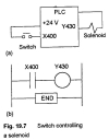
Figure 7 - Switch controlling a solenoid
Another example might be an on-off temperature control (Fig. 8) in which the input goes from low .o high when the temperature sensor reaches the set temperature. The output is then to go from on to off. The temperature sensor shown in the figure is a thermistor connected in a bridge arrangement with output to an operational amplifier connected as a comparator. The program shows the input as a normally closed pair of contacts, so giving the on signal and hence an output. When the contacts are opened to give the off signal then the output is switched off.

Figure 8 - Temperature control system
Such ladder programs can be entered from special keypads or selected from a monitor screen by using a mouse. They can also be specified by using a mnemonic language. However they are entered, the programs are then translated by the PLC into machine language for the benefit of the microprocessor and its associated elements.