

Impedance vector monitoring strategy
for on-line detection of eccentricity
in induction motors
XVII International Conference on Electrical Machines ICEM 2006
Abstract:
An efficient general strategy for monitoring the condition of induction machines is developed and is applied to the detection of the dynamic eccentricity level in smooth air gap machines using the total machine impedance vector as the means of estimating the machine integrity. It is shown that the fault mechanism that is modulating the stator inductances can be more effectively monitored via impedance estimation than current techniques. On the basis of the derived methodology a series of calculations is illustrating the effectiveness of the approach.
Index Terms — Condition Monitoring, dynamic eccentricity, impedance monitoring, induction motor.
I. INTRODUCTION
We call dynamic eccentricity the situation occurring when
the centre of the rotor of a machine is not at its centre of
rotation and therefore the position of the minimum air gap
rotates with the rotor. Dynamic eccentricity may be caused by
misalignment of the shaft, or wear of bearings, defective
installation, bent shafts, etc. The level of dynamic eccentricity
can be a good indicator of the condition of a machine. Careful
attention to this parameter is even more necessary in induction
machines, which have smaller air gaps between the rotor and
the stator than many other types of machines.
The influence of the fault on flux harmonics, unbalanced magnetic pull, vibratory forces, losses and torque, fluctuations in the line currents were some of the areas of particular interest of the research [2, 3, 4, 5]. Dorrell [6] demonstrated the algorithm for the calculation of unbalanced magnetic pull based on generalised conductor harmonic. The work of Cameron et al. [2] was investigated further by Dorrel et al. [5] by looking at the combined effects of static and dynamic eccentricity. Htsui and Stein [8] used the shaft voltage signals to detect eccentricities and shorted rotor turns in synchronous machines. In an alternative procedure Cardoso et all [9] used the Park’s Current vector approach to monitor the machine condition by plotting the machine current loci for the various machine conditions. Work aiming at simulation of dynamic eccentricity was also carried out [7, 10].
In this contribution we are going to develop an efficient general strategy for monitoring the condition of induction machines and we will apply the method to the detection of the dynamic eccentricity level in smooth air gap machines using the total machine impedance vector. The method is an improvement on the Park’s Vector approach [9]. Current techniques have the disadvantage of using a signal containing a bulk of unused information. Discrepancies between faulty and healthy conditions are superimposed on a widely varying signal for all conditions and therefore difficult to uncover.
II. IMPEDANCE VECTOR TOTAL
The magnetic effects, in the case of dynamic eccentricity,
originate from the variations in the air gap length, and the
consequent distortion of the air gap flux density distribution.
In machines with dynamic eccentricity, stator coil MMF acts
on an air gap with varying length, and hence so far as a stator
coil is concerned the air gap permeance varies as a function of
rotor rotation. The rotor coils are, however, placed differently
in space with respect to the minimum air gap, but they are not
moving. The three rotor coil MMFs act on constant air gap
lengths (but not the same ones).
The result of the distortion of the air gap permeance as described above and, as a consequence of the flux linkage, is a combined variation of the total machine impedance. When we refer to total machine impedance seen at the machine terminals we have in mind the classic steady state equivalent circuit of the induction machine. In the paper, the steady state total impedance expression is derived based on phasor equations.
The idea of impedance vector monitoring is based on instantaneous quantities, not the phasors and is valid for steady state and transient regime. The derivation of the steady state expression is done for guidance of where the operating points at any loading condition are going to be and of course to clarify the dependence on the machine parameters.
Let us refer to the basic steady state phasor equations of symmetrical induction machines [1]:
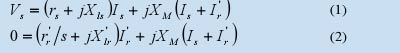
since for any circuit:
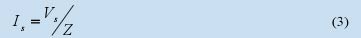
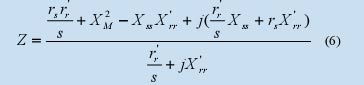
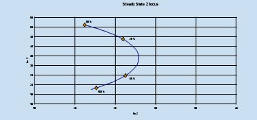
Fig. 1. Total impedance variation due to load change
As can be observed from Fig. 1 in a symmetrical machine at steady state the impedance represents a point on the complex two dimensional space for any single loading condition.
III. DETERMINATION
OF THE FAULT EFFECTS ON
THE COMPONENTS OF TOTAL IMPEDANCE
The magnetic effects, in the case of dynamic eccentricity,
originate from the variations in the air gap length, and the
consequent distortion of the air gap flux density distribution.
We can write the permeance in the air gap as:
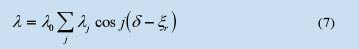
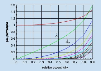
Fig. 2 Amplitudes of the permeance harmonics
Let us define reference frames as in Fig. 3. One sD-sQ - reference frame fixed to the stator, an rD-rQ - rotating reference frame fixed to the rotor. The minimum air gap, which rotates with the rotor angle, is located at an angle from the rotor datum. The rotation angle is defined as ωrt .
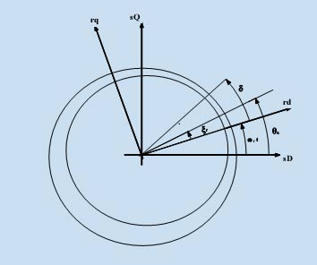
Fig. 3 Definition of the reference frames
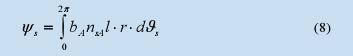
The flux linkage with stator phase A winding can be calculated using the integral:
By following the procedure explained in detail in [10] we arrive at the following expressions for the mutual and self inductances of a machine having dynamic eccentricity expressed in the rotor reference frame:
Lsd - Stator direct axis self inductance
Lsq - stator quadrature axis self inductance
Lrd - rotor direct axis self inductance
Lrq - rotor quadrature axis self inductance
Ldq - cross coupling inductance
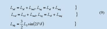
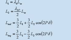
A careful look at the above parameters (9) indicates that the instantaneous value of the eccentric machine impedance will no longer be of a single constant value. The main effect of such a fault on a machine is for the field to become elliptic. The greater the value of eccentricity, the greater will be the value of λ2p and hence the greater the asymmetry.
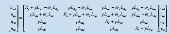
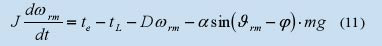
The model used to generate the current and voltage values is the general model developed in [10], in matrix form the equations expressed in the rotor reference frame are as follows:
IV. CALCULATIONS AND RESULTS
At the machine terminals one can easily measure the three
phase instantaneous currents and voltages using current and
voltage probes and data acquisition board with sample and
hold availability, for simultaneous sampling. From the three phase data isA, isB, isC, usA, usB, usC, collected online, the D-Q axis quantities iD, iQ, uD, uQ, can be calculated continuously using the Park’s transformation given in (12)
where, the two axes values can be obtained by replacing
f quantities with i and u:
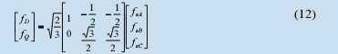
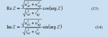
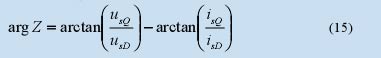
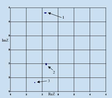
Fig. 4 Impedance Loci for 30% dynamic eccentricity: (1)-loaded at 25%, (2)-loaded at 65% and (3)-full load
The impedance trajectories for the three loading conditions shown in Fig. 4-6 are placed or centered on the calculated steady state curve shown in Fig. 1. As expected in the case of 30% eccentricity, shown in Fig. 4, the asymmetry causes variation of the total machine impedance in a small range and as Fig. 5 and 6 demonstrate, as the fault develops it manifests itself in a further variation of the total impedance.
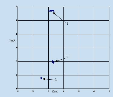
Fig. 5 Impedance Loci for 50% dynamic eccentricity: (1)-loaded at 25%, (2)-loaded at 65% and (3)-full load
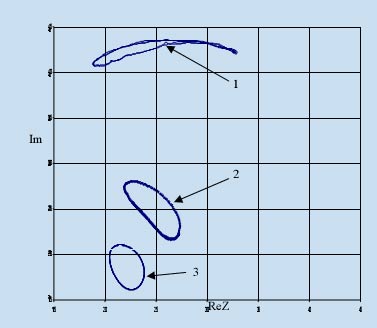
РFig. 6 Impedance Loci for 80% dynamic eccentricity: (1)-loaded at 25%, (2)-loaded at 65% and (3)-full load
V. CONCLUSION
The idea of impedance vector monitoring for identifying
dynamic eccentricity is very promising since the procedure for
its implementation is simple and the means for achieving it not
very expensive. Further investigation is required to establish
the tolerances of its application using practical experimental
data.
ССЫЛКИ
[1] P. C Krause, O. Wasynczuk., S. D. Sudhoff, "Analysis of Electric Machinery", IEEE Press, 1994.
[2] J. R. Cameron, W. T. Thomson, A. B. Dow, "Vibration and current monitoring for detecting air gap eccentricity in large induction motors", Proc. IEE Vol. 133, Pt. B, No 3, 1986, pp 155-163.
[3] F. Notelet, G Ravalitera, "Assessment of the induction motor eccentricity deduced from the fluctuations of the feeding currents", Proceedings of ICEM 84, Lausanne, Switzerland, 1984, pp. 1177-1179
[4] D. G. Dorrell, "The effects of dynamic rotor eccentricity in cage induction motors", Proc. UPEC, Univ. Collage Galway, Sept. 1994, pp. 402-405.
[5] D. G. Dorrell, W. T. Thomson, S. Roach, "Analysis of Airgap Flux, Current and Vibration Signals as a Function of the Combination of Static and Dynamic Airgap Eccentricity in 3-phase induction motors", IEEE Trans. on IA, Vol. 33, no 1, 1997, pp. 24-34.
[6] A. Stavrou, J. Penman, " The on-line quantification of air-gap eccentricity in induction machines", Proc. International Conference on Electrical Machines '94, Paris, France, 5-8 September 1994, pp. 261-266.
[7] H. A. Toliyat, M. S. Arefeen, A. G. Parlos, "A method for Dynamic Simulation and Detection Air-Gap Eccentricity in Induction Machines", IEEE Trans. IA, Vol.32, no 4, 1996, pp.910-918.
[8] J. S. Htsui, J. Stein, "Shaft signals of Sailient-Pole Synchronous Machines for Eccentricity and Shorted-Field-Coil Detections", IEEE Trans. On EC, Vol. 9, no 3, 1994, pp. 572-578.
[9] A. J. M. Cardoso, E. S. Saraiva, M. L. S. Mateus, A. L. Ramalho, :"On-line detection of air gap eccentricity in 3-phase induction motors, by Park's vector approach", IEE 5th International Conference on Electrical Machines and Drives, Conf. Publ. No 341, London, UK., 1991, pp 61-66.
[10] A. Stavrou, J. Penman, "Modeling Dynamic Eccentricity in Smooth Air-Gap Induction Machines", Proc of the IEEE International Electrical Machines and Drives Conference '01 Conference CD, Boston, USA, June 2001.