

Detection of the Combination of Static and
Dynamic Air gap Eccentricity in 3-Phase
Induction Motors using Stator Current
Monitoring
XVII International Conference on Electrical Machines ICEM 2006
Abstract-- This paper deals with the application of Stator Current Monitoring (CSA), for detection of the combination of static and dynamic air gap eccentricity in 3-Phase induction motors. Three-phase IM are the “workhorses” of industry and are the most widely used electrical machines. In industrialized nations, 70% of industrial processes use the induction motor. For this reason, detection of incipient motor failures is very important, thereby avoiding production lost and reducing operational costs. The main idea of motor damage detection leads with “motor variables, currents, flux, electric torque and power, variations (in particular the spectrum) with respect to the normal time-varying operating conditions of the motor”. MCSA is a noninvasive on line monitoring technique to diagnose faults in three-phase IM by differences detection between fault and normal conditions, in current spectrum. Experimental tests were realized in IM of small power, and the results will be validated in later works with a representative quantity of motors.
Index Terms—Static Eccentricity, dynamic eccentricity, motor diagnostics, motor current signature analysis, frequency analysis.
1. NTRODUCTION
Three-phase induction motors are the most robust of the
industry and are the electrical machines more widely used.
The induction motors are used in almost 70% of the industrial
processes. For this reason the importance of incipient motor
failures detection. The early motor failures detection and a
good prediction avoids the production loss and therefore the
economic losses. The main idea of motor damage detection
leads with "motor variables, currents, flux, electric torque and
power, variations (particularly the spectrum) with respect to
the normal time-varying operating conditions of the motor".
Motor Current Signature Analysis (MCSA) is a noninvasive, on-line monitoring technique to diagnose faults in three-phase induction motor drives, by differences detection between fault and normal conditions in the current spectrum. Induction Motors can operate with asymmetries, such as:
- Stator windings failures (inter-turns or short circuits)
- Broken rotor bars and end ring faults.
- Mechanical failures (bearing damage, motor shaft failures or air gap eccentricities).
Asymmetric induction machine operation produces asymmetric fluxes, unbalanced currents, pulsed torques and losses increase. Final results can be efficiency reduction and excessive temperature increase, which could lead to an early isolation failure on the machine. Thus the detection of incipient failures is very important to increase the time life of the electrical machine. A failure in the electric motor can be established by detecting some variations in the input currents (stator currents), torque or flux compared with normal operation variables [1]. Static and Dynamic Air gap Eccentricity are produced by damage bearings and/or motor shaft failures [2]. Actually bearings are one major cause of failures in rotating machines [3] Using the monitoring of noise, vibration and temperature is possible its detection. The implementation of these measuring systems could be expensive and probably only proves to be economical and practical in the case of large motors or critical applications. During the past 20 years, there has been a substantial amount of research into the development of new condition monitoring techniques for induction motors.
One successful technique is the Motor Current Signature Analysis (MCSA) [4]. This paper deal with the application of MCSA of Static & Dynamic Air gap Eccentricity in Induction Motors.
2. HEORETICAL ANALYSIS
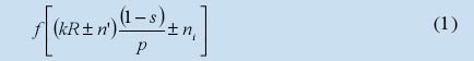
Eccentricity related faults: Machine eccentricity is the condition of unequal that exists between the stator and rotor [5]. When eccentricity becomes large, the resulting unbalanced radial forces (also known as unbalanced magnetic pull or UMP) can cause stator to rotor rub, and this can result in the damage of the stator and rotor. Rotor eccentricity in induction motors takes two forms, static eccentricity (where the rotor is displaced from the stator bore center but is still turning upon its own axis), and dynamic eccentricity (where the rotor is still turning upon the stator bore center but not on its own center). The causes of either type of rotor eccentricity are many, worn bearings, a bent rotor shaft, mechanical resonance at a critical speed, etc. In reality both static and dynamic eccentricities tend to co- exist. An inherent level of static eccentricity exists even in newly manufactured machines due to manufacturing and assembly method, as has been reported by Dorrell [6]. This cause a steady unbalanced magnetic pull (UMP) in one direction. With usage, this may lead to bent rotor shaft, bearing wear and tear, etc. This might result in some degree of dynamic eccentricity. Unless detected early, these effects may snowball into stator to rotor rub causing a major breakdown of the machine [7]. The presence of static and dynamic eccentricity can be detected using MCSA [8]. The equation describing the frequency components of interest is

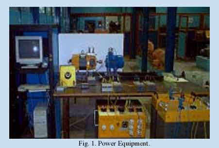
A brief description of the acquisition data systems and of the power equipments, it is described in the following section.
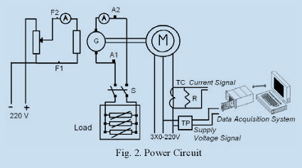
3. MONITORING OF THE INPUT CURRENT
Instantaneous current monitoring implementation has been
shown in Fig. 1. It shows the induction motor, supply source,
load motor (DC generator), and the resistive load. To the left,
the data acquisition system can be observed, that is basically a
computer with an acquisition card. The acquisition card
converts stator current and voltage analog signals to digital
quantities.
- M: IM, 2 HP, 220 V, 1680 rpm, Y, PF 0.76, 60 Hz;
- G: DC Generator 2.2 kW, 230 V, 1800 RPM;
- Load: Resistance Box TB 40, 3.3 kW;
- R: Resistance Measurement includes seven shunts resistances of 120 ohms, 1/4 watts each;
- PT: Voltage Transformer 200/10.
- CT: Current Transf. YEW, 10/1, 60 Hz, class 1;
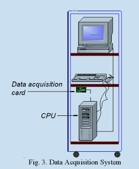
Data acquisition system has the following elements: Signals conditioning equipment, Data acquisition card, and software to drive the Data acquisition card. The acquisition system is detailed in Fig. 3. The data acquisition target is AT- MIO-16DE-10, with 16 single ended or 8 differential inputs, 12 resolution bits, Max. Sampling rate 100 KS/s, 32 digital input-outputs, 2 analog outputs, 2 counter/timers 32 bits, bipolar input range 10 volts. On the other hand, the language program used was LabVIEW, version 5. LabVIEW contains a comprehensive set of tools for acquiring, analyzing, displaying, and storing data, besides is used to communicate with hardware such as data acquisition, vision, and motion control devices.
The software LabVIEW was chosen to show the input current. LabVIEW programs are called virtual instruments, or VIs, because their appearance and operation imitate physical instruments, such as Oscilloscopes and Multimeters. Lab VIEW contains a comprehensive set of tools for acquiring, analyzing, and storing data. Three virtual instruments were designed in this work: Virtual Instrument 1:
o To Acquire and to save current and velocity; Virtual Instrument 2:
o To read current and velocity; Virtual Instrument 3:
o To read and to compare currents with healthy motor and with static and/or dynamic eccentricity air gap in induction motor.
4. EXPERIMENTAL RESULTS
Experimental verification was carried out on a standard
220 V, 2.0 Kw, 4-pole cage induction motor connected to a 60
Hz supply. Bearing were damaged by grease contamination.
Tests were carried out at full rated voltage with varying
degrees of both static and dynamic eccentricity. Six load
points were used and the average taken of the acquisition of
20 spectrums of the line current for a same condition of load
(no variation in line current due to eccentricity was observed).
With the motor uncoupled the line current was 1.8 A, at a slip
0.03 the current was 3 A, and at full load (s = 0.05) the current
was 3.8 A. A. Tests with the healthy motor.
Tests were carried out with the next values:
f1 = 60Hz
n = 1
n’= 0 for static eccentricity and 1 for dynamic eccentricity.
p = 2
R = 36
ni = 1
These tests showed the next results:
A1.-Tests with motor uncoupled, (s= 0.003594):
In this case (fig. 4):
1. - The frequency of static eccentricity was 1137.31 Hz, and the magnitude for this frequency was 63.39 db.
2. - The frequency of dynamic eccentricity (n’=1) was 1166.78 Hz, and the magnitude for this frequency was 91.00 db.
3. - The frequency of dynamic eccentricity (n’=1) was 1106.68 Hz, and the magnitude for this frequency was 91.81 db.
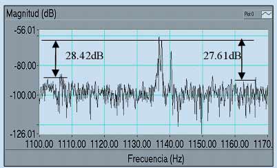
Fig. 4 Tests with the healthy motor uncoupled.
A2.-Tests with s = 0.044082 ( 83.78% of load):
In this case (fig. 5):
1.- The frequency of static eccentricity was 1093.39 Hz, and the magnitude for this frequency was 60.48 db.
2.- The frequency of dynamic eccentricity (n’=1) was 1122.08 Hz, and the magnitude for this frequency was 88.47 db.
3.- The frequency of dynamic eccentricity (n’=1) was 1063.19 Hz, and the magnitude for this frequency was 90.84 db.
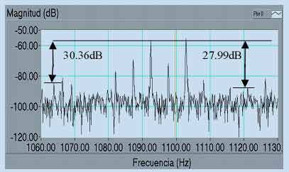
Fig. 5 Tests with the healthy motor, s= 0.044082.
A3.- Tests with full load, (s = 0.052777):
In this case (fig. 6):
1. - The frequency of static eccentricity was 1084.09 Hz, and the magnitude for this frequency was 64.92 db.
2. - The frequency of dynamic eccentricity (n’=1) was 1112.28 Hz, and the magnitude for this frequency was 91.84 db.
3. - The frequency of dynamic eccentricity (n’=1) was 1055.19 Hz, and the magnitude for this frequency was 89.90 db.
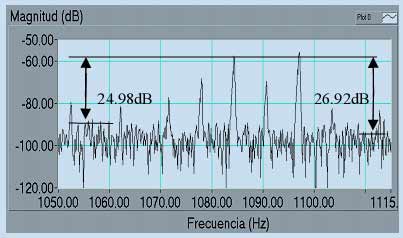
Fig. 6 Tests with the healthy motor, s= 0.052777.
B. - Tests with static and dynamic eccentricity air gap.
B1.-Tests with motor uncoupled (s=0.004491).
In this case (fig. 7):
1. - The frequency of static eccentricity was 1164.98 Hz, and the magnitude for this frequency was 53.02 db.
2. - The frequency of dynamic eccentricity (n’=1) was 1164.98 Hz, and the magnitude for this frequency was 73.94 db.
3. - The frequency of dynamic eccentricity (n’=1) was 1105.78 Hz, and the magnitude for this frequency was 63.30 db.
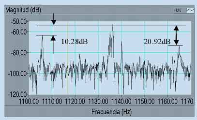
Fig. 7 Tests with static and dynamic eccentricity air gap in motor uncoupled.
B2.-Tests with s = 0.046624 ( 83.78% of load):
In this case (fig. 8):
1. - The frequency of static eccentricity was 1090.29 Hz, and the magnitude for this frequency was 55.69 db.
2. - The frequency of dynamic eccentricity (n’=1) was 1118.88Hz, and the magnitude for this frequency was 66.45 db.
3. - The frequency of dynamic eccentricity (n’=1) was 1061.69 Hz, and the magnitude for this frequency was 62.37 db.
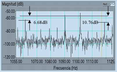
Fig. 8 Tests with static and dynamic eccentricity air gap, s=0.046624.
B2.-Tests with s = 0.056508 ( full load):
In this case (fig.9):
1. - The frequency of static eccentricity was 1078.89 Hz, and the magnitude for this frequency was 56.22 db.
2. - The frequency of dynamic eccentricity (n’=1) was 1107.18Hz, and the magnitude for this frequency was 66.81 db.
3. - The frequency of dynamic eccentricity (n’=1) was 1050.59 Hz, and the magnitude for this frequency was 60.71 db.
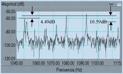
Fig. 9 Tests with static and dynamic eccentricity air gap, s=0.056508.
5. RESULTS
The results show clearly that the magnitude for frequency of static and dynamic eccentricity air gap grow with failure Besides, the difference between magnitude for frequency of static eccentricity and dynamic eccentricity is bigger with damaged motor. Then, it’s possible to establish if the motor has eccentricity problems analyzing the spectrum current.
The Table 1 shows the values of differences between the magnitude of the harmonics for frequencies of static and dynamic eccentricity for considering good, acceptable or unacceptable eccentricity. These ranks were obtained of the analysis of the acquisitions.
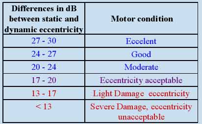
Table 1: Motor Condition.
6. CONCLUSION
This work describes a theoretical-experimental
methodology that has been implemented to determine
incipient failures in industrial induction motors.
This paper shows the rank between the harmonic magnitudes of the static and dynamic frequencies to consider acceptable or unacceptable eccentricity, independently of the load connected.
The implemented experimental assembling and the data acquisition system will allow the authors to continue this investigation line.
REFERENCES
[1] S. Nandi and H. A. Toliyat, “Condition monitoring and fault diagnosis
of electrical machine – a review” en Proc. IEEE_IAS Annual Meeting
Conference’99, vol. 1, Phoenix, AZ, Oct. 1999, pp. 197-204..
[2] William T. Thomsom, D. Rankin. and D. G. Dorrell, “On-line Current Monitoring to Diagnose Airgap Eccentricity in Large three-Phase Induction Motor – Industrial Case Histories Verify the Preditions”. Paper. IEEE Transactions on energy conversion, vol 14. No 4, December 1999. Pp 1372-1378.
[3] Eva Monagas y Maria Mago, “Fallas mas comunes en los motores de induccion de empresas del sector industrial del Edo. Carabobo” ,Trabajo de Ascenso, Universidad de Carabobo, Barbula, Venezuela, Enero 2004.
[4] R. Schoen, T. Habetler, F. Kamran, and R Bartheld, “Motor bearing damage detection using stator current monitoring”, IEEE Trans Ind. Applicat., vol.31, no. 6, pp. 1274-1279, Nov./Di. 1995.
[5] J. R. Cameron, W. T. Thomson, and A. B. Dow, “Vibration and current monitoring for detecting air gap eccentricity in large induction motors”, IEE Proceedings, pp. 155-163, vol. 133, pt. B, no. 3, May 1986.
[6] D. G. Dorrel, W. T. Thomson and S. Roach, “Analysis of air gap flux, current, vibration signals as a function of the combination of static and dynamic air gap eccentricity in 3-phase induction motors”, IEEE Trans. Ind. Appln, vol. 33, No. 1, pp. 24-34, 1997.
[7] S. Williamson and P. Mirzoian, “Analysis of cage induction motor with stator winding faults”, IEEE-PES, Summer Meeting, July 1984.
[8] P. Vas, “Parameter Estimation, Condition Monitoring and Diagnosis of Electrical Machines”, Clarendon Press, Oxford, 1993.
[9] S. Nandi and H. A. Toliyat, “Detection of Rotor Slot and other Eccentricity Related harmonics in a 3-phase Induction Motor with different Rotor Cages”, to appear in IEEE-PEDES’98 Conference – roceedings, Perth, Australia, Nov. 30-Dec.3,1998.
[10] A. Ferrah, P. J. Hogben-Liang, K. J. Bradley, G. M. Asher, M. S. Woolfson, “The effect of rotor design of sensorless speed estimation using rotor slot harmonics identified by adaptive digital filtering using the maximum likelihood approach”, IEEE-IAS annual meeting conference recordings, Pp. 128-135, New Orleans, Lousiana, Oct. 5-8, 1997.
[11] J. Penman, H. G. Sedding, B. A. Lloyd, W. T. Fink, “Detection and location of interturn short circuits in the stator windings of operating motors”, IEEE Trans. Energy Conv., vol. 9, No. 4, Dec 1994.
[12] S. Nandy, RajMohan Bharadwaj, H. A. Toliyat, A. G. Parlos, “Performance analysis of a three phase induction motor under incipient mixed eccentricity condition”, to appear in IEEE PEDES’98 Conference Proceedings, Perth, Australia, Nov. 30- Dec.3, 1998.