
Faculty: Electrical Engineering
Speciality: Electric Drive and Industrial Installation Automation
In the modern industry the big share among all hoisting-and-transport mechanisms is occupied with cranes to which various functions are assigned: raw materials transportation, finished goods moving, installation and equipment repair.
One of the main features of cranes is that in most cases a cargo with movement gear is connected not rigidly but with the means of elastic bracings that is the main cause of the appearance of swaying in horizontal movement of the cargo. Cargo swaying appears during start-up and braking of movement gear and slewing gear of the crane. Swaying considerably increases work cycle time, causes fluctuations of the torque and uneven crane movement, increases valve recession of some units, and in some cases can lead to the danger of cargo and object collision. Also the cargo sway has special importance in crane automation and for cranes which carry out exact mounting operation. This sways don’t stop for a long time because of low air resistance and rope rigidity. That is why it is necessary to apply anti-sway measures.
The purpose of the work is to research different anti-sway methods in crane electromechanical systems. To get an assigned aim it is necessary to solve next problems:
There are not enough works which completely and thoroughly open all the questions connected with sway damping in systems with elastic bracings.
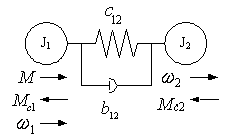
Design model of the most general two-mass mechanical part of the electromechanical system is shown in fig. 1. On this model all the values are reduced to the motor velocity and mean: J1 and J2 – inertia moment of the first (the motor rotor) and second (the suspended cargo) mass; w1 and w2 – their angular velocities; c12 and b12 – equivalent coefficient of rigidity and a viscous friction of an elastic link;M – the motor torque; Mc1 and Mc2 – drag torques of the first and second mass, which for simplification represent the torque of a dry friction.
The system of the equations of the two-mass mechanical part is

According to the received equations it is possible to make block schematic diagram of mechanical part according to the received equations, which is shown in the fig. 2.
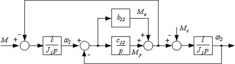
On the block schematic diagram are depictured:
Mв=b12(w1-w2) – viscous friction torque,
 – elastic link torque.
For the calculation of the cargo sway process it is comfortable to use a design model, which is in the fig. 3.
In the point M the masses of rotary elements of the movement gear and translatory moving parts are concentrated (m1). In the point K cargo mass m2 is concentrated. The differential equations of cargo movement:
 ; (2)
; (2)where F(t) – accelerating or decelerating influence, which is applied in point M and generally depends on time; S0 – тcurrent distance from the trolley to reference point in the fixed coordinate system; S – amplitude of cargo sway in the moving coordinates.
Transformation of the equation (2) leads to the equation:
 ; (3)
; (3)General solution of the equation (3) with zero initial condition and constant force F(t) during the acceleration or deceleration periods will be of the form:
 ; (4)
; (4)Maximum amplitude of cargo sway will be equal:
 ; (5)
; (5)The cargos sway frequency:
 ; (6)
; (6)The derivative from (4) gives the following result:
 ; (7)
; (7)From the formulas (4) and (7) follows that in a time interval:
 ; (8)
; (8)a cargo deflection S and velocity vK will be equal 0, where n=1, 2, 3... is the quantity of cargo sway. In the other way swaying remains and their amplitude depends on initial conditions.
There are different ways of sway damping and methods of their realization. The most simple and less effective of them are [12]:
Among the most perspective and giving good results following method can be singled out:
1) Those which are based on the determination of the sway period:
2) Modal control [10].
3) Those which are based on the application of the intellectual units, such as
In a course of researching in Simulink/Matlab according to the fig. 1 the model of asynchronous electrical drive with two-mass mechanical part was designed. The sway period and amplitude conforms to formulas (5) and (6).
Following anti-sway methods was modeled:
1. Control that is optimal at performance. The results of modeling are in fig. 5.
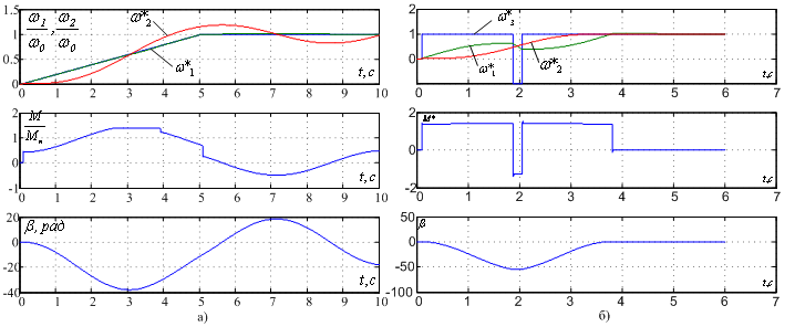
Fig. 5 illustrates that using this anti-sway method cargo sways stop to the end of
acceleration ( ), in spite of the first cargo deflection
rather bigger than in a system without sway damping.
), in spite of the first cargo deflection
rather bigger than in a system without sway damping.
2) Half-velocity acceleration method.. РThe results of modeling are in fig. 6.
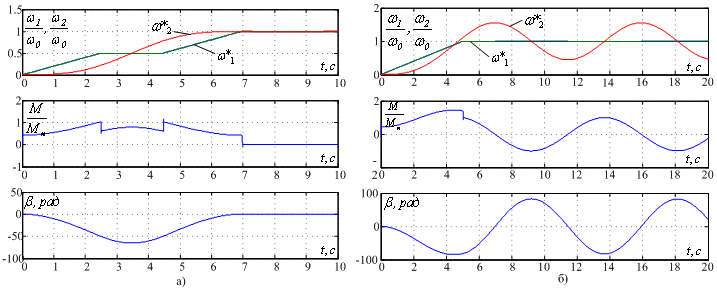
Fig. 6 illustrates that after acceleration cargo sway stops
(). When using this method the first cargo deflection is not
bigger than in a system without sway damping. However start-up is rather prolonged that when using optimal performance
control.
In the course of further research it is planned to design and model anti-sway system with FUZZY-controller and with artificial neuron networks.