
Source of information: 22nd International Symposium on Automation and Robotics in Construction ISARC 2005 - September 11-14, 2005, Ferrara (Italy)
In the last few years, automation of slewing cranes is gaining more and more importance in transport and handling processes. However, each operation of crane with rope-suspended loads provokes swaying movements of load. Neutralization of these swaying movements represents a key problem when high handling speeds, operational reliability, accurate traveling trajectories and positioning are required. Parameter variations and force interactions between rotary and translation movements in slewing cranes call for a special approach when designing the control scheme. The presented paper deals with optimal control of slewing cranes. It will show that optimal control strategy copes very well with the mentioned problems.
Index Terms — slewing crane, modeling, anti-sway, optimal control
Common drive control systems are usually designed in cascade structure and optimized using linear standard criteria (Betragsoptimum, symmetrical optimum) with PI-controller. Current limitation is realized by current reference value limitation. This structure becomes accepted in practice because of its easy implementing. Specific technological tasks can be taken into consideration by overlaid control loops that provide the appropriate reference values for the drive system. This structure can be maintained in the proposed robust control scheme of slewing cranes. However, robust and optimal control theory starts from the state space description of the plant and optimal controller parameters are given in state space notation as well. However, for practical applications the obtained control structure can be easily transformed into cascade structure, so the presented optimalcontrol structure does not lose its generality.
Mathematical description of slewing cranes movement differs considerably from gantry cranes and overhead traveling cranes. Crane movement is characterized by the appearance of Coriolis and centrifugal forces. Consequently, the system of governing equations is becoming significantly non-linear and the application of linear control theory methods may lead to problems. Practical and simulation investigations prove that both components may considerably influence the movement of slewing cranes and that they must by taken into account when designing and optimizing the controller system. To solve this problem, three different approaches can be utilized:
It is obvious that the first mentioned two methods starts from the supposition of a well known and defined plant model, the parameter finding of which, however, in practice may cause problems. Moreover, it can be assumed that handling tasks for slewing cranes do not require extremely high position nor travel trajectory accuracy. On that condition it seems to be interesting to utilize a control strategy that features robustness in the whole range of possible parameter variations as well as Coriolis and centrifugal forces too which, in addition, guaranties necessary motion quality. To this aim in the last few years several sophisticated control methods have been developed. Although their mathematical description in control theory books is sometimes confusing they can be easily realized in practice. In the following the implementation of a LQ-controller for slewing crane movement control shall be considered.
Optimal control systems meet a criterion that depends on the control task. LQC (linear quadratic controller) are of particular practical interest. Here the weighed quadratic medium value of the state variables (e.g. error) and control variable are minimized.
This controller design represents a compromise between the maximum obtainable dynamics and the maximum value of the control variable. It is obvious that an increasing weight of the control variable u goes along with a deterioration of dynamics. Determination of the feedback parameters leads to the well known Ricatti equation that can be solved off-line and does not represent problems when using appropriate software. It is known that LQC is characterized by good robustness against parameter variations [1] and is consequently suitable for system control with uncertain or varying parameters.
In control theory norms are utilized for performance assessment (performance index) [2], [3]. So the H2 - norm of a signal u

can be interpreted as medium power of the signal whereas the  -norm
-norm

gives the signal maximum value in the interval  . In control theory
the -norm of a transfer function F(s) is determined by the maximum
amplitude in the bode plot or rather by the farthest distance from the origin in the Nyquist plot, i. e.
. In control theory
the -norm of a transfer function F(s) is determined by the maximum
amplitude in the bode plot or rather by the farthest distance from the origin in the Nyquist plot, i. e.
 (4)
(4) It can be shown that there is a direct correlation between system sensitivity against
parameter variations and the -norm. The larger the -norm the more sensitive
the system is against parameter variations. Then the problem of controller design consists in choosing the state
variable feed backs in a way not to exceed a maximum allowable value  for the
-norm of the state variables. The influence of the norms of respective
state variables on the final solution is determined, similar to the LQC, via weight factors. However, here the
weights are chosen depending on frequency, so definite frequency spectrums can be suppressed or taken into particular
consideration. Thus in addition to robustness against parameter variations insensitivity to perturbations in a
definite frequency range can be obtained.
for the
-norm of the state variables. The influence of the norms of respective
state variables on the final solution is determined, similar to the LQC, via weight factors. However, here the
weights are chosen depending on frequency, so definite frequency spectrums can be suppressed or taken into particular
consideration. Thus in addition to robustness against parameter variations insensitivity to perturbations in a
definite frequency range can be obtained.
To describe axis movement of the slewing crane, the equivalent cinematic scheme
with concentrated masses represented in figure 1 is utilized. The crane has 5 independent degrees of freedom
(DOF): trolley movement (x coordinate), slewing gear rotation ( coordinate), hoisting gear movement (coordinate l) and the two orthogonal sway angles in trolley movement
direction and perpendicular to it (
coordinate), hoisting gear movement (coordinate l) and the two orthogonal sway angles in trolley movement
direction and perpendicular to it ( and
and  respectively). The task consists in load positioning along a desired trajectory with given accuracy using a
position controlled drive system for the trolley, slewing and hoisting gear. Using the Lagrange formalism the
system of governing equations can be obtained in the following general form
respectively). The task consists in load positioning along a desired trajectory with given accuracy using a
position controlled drive system for the trolley, slewing and hoisting gear. Using the Lagrange formalism the
system of governing equations can be obtained in the following general form

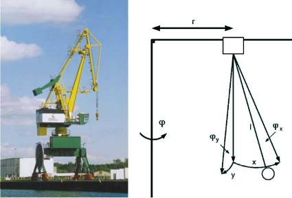
Figure 2 depicts equation (5) with
M – motor torque,
q – generalized coordinates,
J – Jacobi matrix,
B – matrix of vicious friction,
C – coupling matrix to calculate Coriolis and centrifugal effects,
G – Gravitation matrix
This notation is a general description of coupled movements that is widely used in robotics. If we start from the supposition that trolley, slewing and hoisting gears are equipped with position controlled drive systems; their coordinates can be given by the respective reference trajectory, and all force actions of the load on the trolley can be neglected. Thereby the overall scheme of the sway movement can be simplified as shown in figure 3. The controller system will be designed for a simplified linear sway model without respect of the coupling forces and taking into account a medium rope length. However, the controller shall provide satisfactory system behavior both when rope length is changing and when Coriolis and centrifugal forces are acting during crane movement.
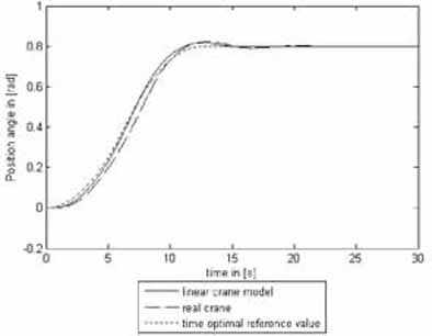
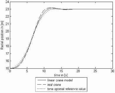
The influence of Coriolis and centrifugal forces of the uncontrolled system can be assessed from the pictures 4 and 5. Here the reference trajectories are optimized for the linear model with constant rope length. For the slewing crane model trolley, slewing and hoisting gear are working simultaneously and Coriolis and centrifugal accelerations are represented separately when. Trolley gear is moving from 15 m to 23 m at maximum speed 1,26 m/s, slewing gear is rotating from 0 to 0,8 rad at maximum speed 0,126 rad/s and rope length is increasing from 36 m to 52 m at maximum speed 2,5 m/s.
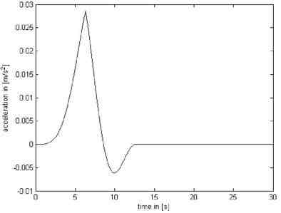
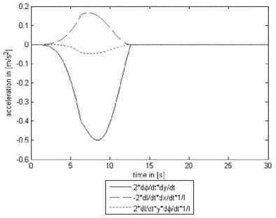
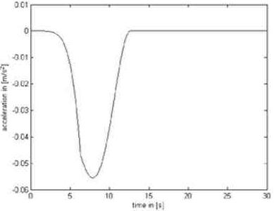
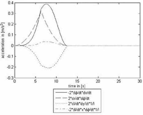
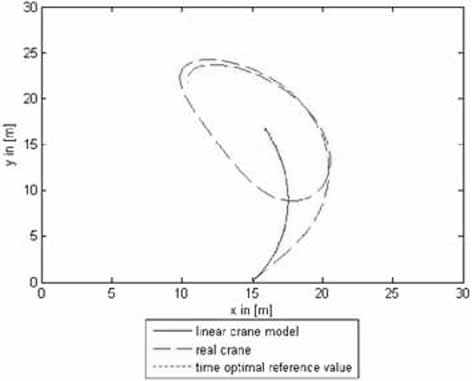
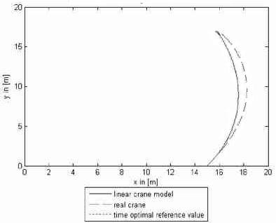
Figure 6 pictures the bird’s eye view of the cargo movement for the linear model and the slewing crane with respect of the mentioned force interactions and rope length variation. It is obvious that the nonlinear effects causes considerable load swaying whereas the linear model is reproducing the optimal trajectory without swaying.
When choosing the drive structure we start from the supposition that a desired load movement trajectory is given to the reference trajectory generator. This trajectory is calculated for the linear sway model and shall be reproduced by the actual crane. It is obvious that changing rope length, perturbations, and the mentioned force interactions cause deformations of the real crane motion. Superposed control loops are calculating correction positions driving the actual load trajectory to the reference trajectory and compensate the influence of all perturbations. This control mechanism has to guaranty required motion quality in the whole working area, i.e. it must be robust against all mentioned perturbations. Figure 7 illustrates the chosen drive structure for the trolley gear. Here the reference trajectory generator out put is applied both to the real plant and the linear sway model. The latter, consequently, generates the load reference trajectory that must be reproduced by the actual crane. This movement is compared with the actual crane movement and the difference between the two movements is compensated by the state controller.
To verify the theoretical results of investigation, the whole system of governing equation is simulated in MATLAB/Simulinik and a LQC in accordance with [2] is designed. Figures 8 and 9 show the load movement when the trolley and slewing gears are activated simultaneously for varying rope length (from 36 to 52 meters). The controller was designed for the maximum rope length. Figure 10 illustrates the load movement from bird’s eye view. Here must be pointed out that choosing the weight factors of the error value and control value system behavior can be influenced in a wide range.
Slewing crane motion is characterized by changing parameters and force interactions by centrifugal and Coriolis forces. These effects call for the application of robust control strategies. LQ controller are able to cope with these challenges. The presented results for slewing crane control prove good robustness and performance.