|
Olga GrigorivaFaculty: Mining and Geolodgical
|
|---|
|
|---|
|
|---|
ABSTRACTof Mater Qualification Work “3-D BUILDING MODELING AND PHOTOREALISTIC VISUALIZATION USING AERIAL IMAGES”ABSTRACT Aerophotography has been widely used to obtain spatial information over time and it is one of the main data sources for the real world modeling. One such model is the three-dimensional modeling of urban areas. The computer graphics development was opportunity to improve the methods for constructing not only a geometric model, but its model to the real world through photo-visualization. In addition, the aerophotography is the main source for the area and horizontal surfaces texturing. For wall and vertical surfaces texturing is mainly used by ground data survey and photographs of individual objects whith roll film camera and digital camera. This technology is very expensive and cumbersome, because the photographing of all buildings facades almost impossible. Therefore, a using aerial cameras tendency, which are not only designed to plan images object, but his perspective images too. This allows to use aerial survey data of for three-dimensional modeling and visualization model in maximum. The objective of this work is to study different methods three-dimensional geometric city model constructing and its visualization. The main source of spatial data and texture maps are the aerial perspective. This study is implemented by using the digital photogrammetric station «Delta», and software Digitals. As developments tools were used Borland Delphi and graphics library OpenGL, as modeling tools were using software AutoCAD and 3D Studio Max. 1. INTRODUCTION The relevance and usefulness of two-dimensional mapping information is decrease with each day, but the available data don’t respond quickly and effectively to solve engineering problems encountered with the required precision every time. There is a need of accurate simulation models of the real world, which could form the basis for the different situations simulation and decisions on them various tasks. A separate issue is the integration of this model in GIS, but this issue will not be considered at this stage of research. There are many sources of spatial information. One of the simplest and most common is the use of vector map [3]. In this case, to build a terrain model using structural elevation and horizontal lines. Three-dimensional objects produced by extrusion of the trace corresponding to the height of the building floors. As for texturing in this case, often use raster maps, as well as available for this location mosaic. To reduce costs for realistic visualization of 3D objects using artificially created a library of textures, imitating the color and material properties. This technique is discussed in section 2 of this article. When modeling the city one of the main problems is that there are no specially adapted software that would be allowed to perform all phases of complex modeling. Namely, would photogrammetric station, which gives the possibility of obtaining spatial data for aerial photography, mapping system, which allows to process the information, geographic information system to link the model with the attributive and spatial data, as well as high-quality three-dimensional graphics editor. Hence, there is a need to use to build and visualize models of several software products, specializing in a particular stage of processing and a model. The combined use of various products to create a photo-model of the city described in section 3. However, the multiple programs using is not only inconvenient but also costly. Where is easier to obtain the spatial information, and immediately process it. As described above, as the main product at this stage of the research program was selected Digitals. In 2008, the program adapted to the ball of three-dimensional modeling. Even prior to the collection have been designed 3D templates that can immediately get in the cathedral frame model, as already junction. The same features were added to work with textures and management models which are described in more detail in Section 4. 2. DELPHI SIMULATION USING OPENGL The initial data for a model is a paper map of the Donetsk cit. As a result, tracing maps in ArcView GIS 3.2. established base of space (X, Y, Z) coordinates, as well as attribute data base is filled with an object qualifier, floors or the height of the object, the object gap indicator, as well as the color of an object in RGB. Data about the objects were exported in text format. For the simulation of the city in the Delphi programming environment was developed by the application. To display I used graphical library OpenGL. To view elevation models used triangulation irregular network of TIN. In some cases, to model roads used quadrangular polygons, as they correctly simulate the surface. In connection with that area of the object occupies a small area were used and classified the following facilities: a building entrance as part of the building, green areas (lawn), asphalt surface, curb, tram rails, tram and lamppost. The program for each area are different ways of building. Buildings and entrances are built by squeezing ranges in height. Similarly constructed lawns and asphalt coating (described above). Tram rails, on the same streetcar and lamppost draw lines. 3. AUTOCAD AND 3D STUDIO MAX MODELING The initial data for constructing a color aerial images of Haninge, Sweden. The collection of objects implemented in the program Digitals on standard templates collection. To simplify the interpretation of objects and splitting them into segments, a template that already contains the layers needed for digitization. As a result, the collection of information was recorded such items as: border roads, lawns, the characteristic point of relief and some objects, roofs, garages and other buildings, the boundaries of parking lots, lights, etc. The result of digitization presented in Figure 1. 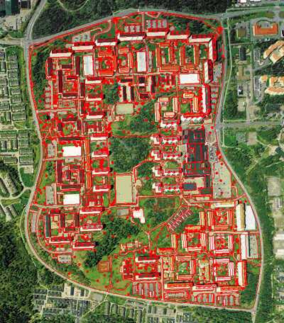 Figure 1 - Images Digitization in Digitals  Figure 2 - Buildings Patterns Анимация: объем - 136Кб, размер - 300х300, количество кадров - 8, задержка между кадрами - 120 мс, задержка до повторного воспроизведения - 0 мс, количество циклов повторения - не ограничено/> More data are exported to AutoCad, where their geometric correction facilities and their direct three-dimensional modeling. Geometric correction was carried out mainly on the buildings in order to correct errors of digitization. At this stage, to simplify the simulation model of creating a library of three-dimensional objects. Library of 3D objects is composed of 31 objects, which are represented by buildings. These templates are now fully geometrically corrected. Terrain model in the model consists of two layers: an asphalt coating and not paved areas. 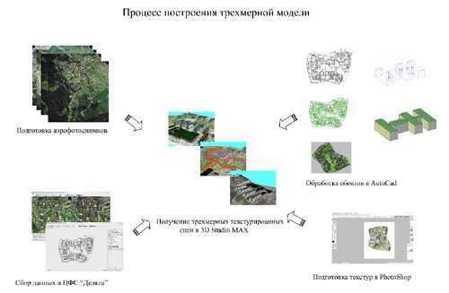 Figure 3 – 3D models building process 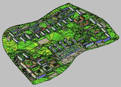 Figure 4 – 3D scene in AutoCAD The ultimate three-dimensional model or a 3D scene is constructed in 3D Studio MAX. To this end, the program is imported model with a 3ds, obtained from AutoCad. On the imported objects are rendered texture that allows for more realistic display model. For visualization was used with a standard visualisation progressive scan, in particular - lighting.  Figure 5 – 3D scene in 3D Studio Max Анимация: объем - 149Кб, размер - 320х240, количество кадров - 3, задержка между кадрами - 180 мс, задержка до повторного воспроизведения - 0 мс, количество циклов повторения - не ограничено 4. MODELLING IN DIGITALS As the main method for constructing 3D-models of cities on these aerial photographs examined by the creation of textured 3D-models in the Digitals. It should be noted that this technology is not aimed at creating a model for close consideration and detail. The initial data is the data library pictometry city of Birmingham, England. Figure 6 presents a general scheme for constructing 3D models of Digitals on advanced imagery. 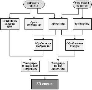 Figure 6 – 3D model constructing scheme Consider the above to create 3D-models. SURFACE DIGITALIZATION. Ongoing measurement points of the earth's surface and the collection of structural relief lines in stereo. DTM / TIN CONSTRUCTION. DTM based on the collected objects in the previous phase, ie objects of relief. If relief is complex, sometimes the best result gives the construction of pre-established DTM TIN. 3D OBJECT COLLECTION. Collection of three-dimensional objects in the layer «3D-model». A feature of this layer is that objects are represented in the faces, not a polyline. For the generation of 3D-buildings in Digitals designed templates collection of buildings (refer to the library).  Figure 7 – Building templates in Digitals Анимация: объем - 194Кб, размер - 250х250, количество кадров - 16, задержка между кадрами - 60 мс, задержка до повторного воспроизведения - 0 мс, количество циклов повторения - не ограничено To automatically projecting walls on the surface of a function of CIR pereprisvaivaniya heights. This function works as follows: For each vertex the brink of an object defined by a point on the DTM. Targets coordinates it remain the same, and the coordinate Z is obtained by interpolation DTM. 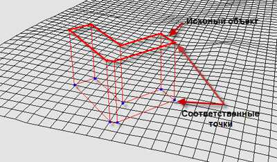 Figere 8 – The result of the heights changes At the same time for each face the wall is determined by the method of interpolation of elevation grounds. The disadvantage of this algorithm is that built the brink may not coincide with the surface, while obrazovyvaya «gaps» between objects. Texturing is carried out in Digitals means open graphics library OpenGL. File with the texture of Digitals stored in the formats BMP, and JPEG. Because OpenGL is not the function of reading / writing of image files, the system handles an array of pixels OpenGL [4]. In order to apply a texture to an object, follow these steps [9, 10]:
Digitals works with two textures (ie Texture coordinates are specified by two parameters). Textures for 3D-objects are generated automatically. 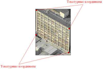 Figure 9 – Texture coordinates 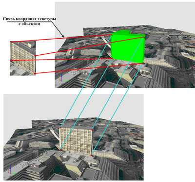 Figure 10 – Texturing result For the 3D-object texturing Digitals designed to automaticaly generate textures. To determine the appropriate facets of the texture restored beam from the brink of the sensor chamber. Restoring rays performed by photogrammetric formulas for the coordinates of points projected facets. To determine whether the edge of the visible, for it restores the normal vector. The above steps are performed for all images containing the image brink. From this set uses the snapshot on which the projection takes the brink of large area, taking into account the visibility of the verge on the image. This function works with a single directory, so all the images used for the texturing should be in the same folder. The selected texture image with the cutting of neighborhood, not to exceed 50 pixels, and stored in a separate file. All texture files are saved in a separate directory «FileName (Textures)» or file textures PAK, located in a folder with a map. At the same time for the layer type «3D model» create table option «Textures», which kept the name and Texture texture coordinates corresponding to the tops of the verge (<file name pattern>, X1, Y1, X2, Y2, X3, Y3, X4, Y4 ). The file name pattern is formed as follows: <Image name for texture><~><Object number><-><Object adge number><.bmp>/<.jpg> Oblect number – unique number of the object, which is the number of objects in the list of map objects (machine room). It is a hidden parameter and is only used within the program. The name of the texture stored in the same order, which lists the brink of the list of points of objects. When you see textured 3D-models for each edge of the object layer «3D model» is carried out according to the imposition of a texture table parameter «Textures» means the library OpenGL. Transformation texture occurs when each load of OpenGL for the world and texture coordinates. For texturing CESDES best mosaic, as it is as close as possible to the planned display of the object model. But in theory, as the texture can be used and inclined shot. Projection texture DTM done by projecting each tayla snapshot. To do this, for the corners of each tyle TIF Tiled (block Typhoid - 256x256 pixels) is its geodetic coordinates. In order to compute the geodetic coordinates of the corners tyle, it is necessary to solve the following problem - to a point on the image to determine the geodetic coordinates. Coordinates taylov angles calculated by the postponement of 256 pixels. 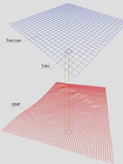 Figure 11 – Tyle projection on the DTM 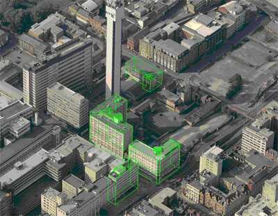 Figure 12 – 3D oblects digitalization. Oblique image 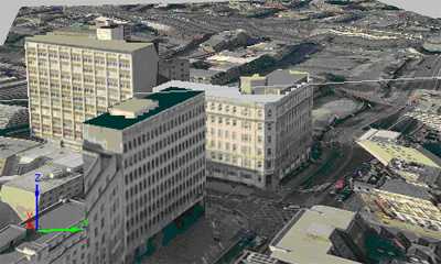 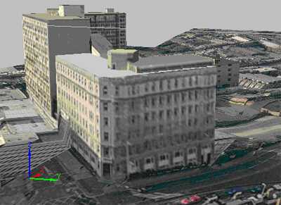 Figure 13 – 3D model texturing (Birmingham, England) 5. CONCLUSION In this paper we examined three methods for constructing three-dimensional models of cities, each of which has both advantages and disadvantages. At this moment the most effective method is to build a 3D photo-model city in the Digitals. The great advantage is the automatic generation of textures, which creates the best texture for the object in a matter of seconds. The bulk of the burden falls on the collection of information, and build on these data, three-dimensional model and its visualization is performed automatically, which can not be said about vysherassmotrennyh methods. However, this method has several shortcomings. First, it is not designed for detailed modeling of objects. For the simulation of topography using DEM, which is more suitable for slaboperesechennoy area and gives incorrect results for complex terrain. Using this technology in the TIN, is unacceptable. It is not always a correct result gives the function pereprisvaivaniya Heights, so between the buildings and terrain model found gaps. Next, the embedded patterns of collecting 3D objects are mostly in the construction of buildings and to build a qualitative model of the city such a classification is not enough. Third, Digitals is a mapping system, so the connection to the model database with attributive information, too, is virtually impossible at this time. Fourthly, the technology is not made for the use of levels of detail, which makes handling of large objects. Fifthly, there is a problem with the data exchange format. To date Digitals not fully support any format that could be used to export the model, but the internal format DMF is not widespread and is not supported by other programs. It should be noted that at the time of publication of the article is not a finished work. It is therefore planned a more detailed treatment of simulation in Digitals to obtain high-quality three-dimensional model visualisation city. REFERENCES
|
|---|
REMARK OF MATERIAL SIGNIFICANCEThe abstract of the Master's work is not complete yet . The final completion in 1st December 2009. Full text of the work and materials on the topic can be obtained from the author or his head after that date. |
|---|
|
© DonNTU 2009 Olga Grigoriva |
|---|