|
ABSTRACT
Actuality of master's work
With the origin of the geological survey boring drilling a requirement appeared in the receipt of the oriented standards of mountain breeds from mining holes for determination of elements of bedding of breeds. It contingently that unlike research of mountain breeds in baring and making standards from single mining holes did not allow to obtain information about the elements of bedding of breeds. For the receipt of reliable information it is necessary to bore even three reconnaissance mining holes. Possibility to study the geological structure of cut on the standards of heaved up the from one mining hole oriented stippler appeared with the origin of method of
kernometry.
In spite of long way which was passed by kernometry in the development, it did not become the inalienable element of geological researches until now. Reasons of it are insufficient perfection of hardwares of receipt of the oriented stippler, heavy tolls of time on their application, reducing the productivity of well-drilling, absence of skilled specialists in this area et cetera Therefore a very
actuallity task is an increase of efficiency of management technology of application and perfection of mechanism for the receipt of the oriented standards of stippler.
Analitik review
Kernometry includes two technological operations: selection of the oriented stippler and determination of elements of bedding of layers, cracks and other visible on a stippler or in the oriented microsections of elements of mountain breed. The oriented is name a stippler with inflicted on his surface a mark position of which is fixed in relation to the ax of mining hole and known direction to tearing away of stippler from a backwall.
In vertical mining holes and mining holes with zenithal corners to 5 utillize a direct orientation. In this case the known direction in relation to which position is fixed well-aimed is consider sending to the magnetic or geographical pole.
In sloping mining holes apply the indirect method of orientation, when position of mark is fixed in relation to an apsidal (vertical) plane.
We will consider classification of methods and hardwares of causing on the stippler of the oriented marks.
For the analys of hardwares and methods of kernometry were undertaken great number of attempts to develop classifications. Classification of M.Kazancev is most
known. In this classification as a basic sign the method of causing is accepted well-aimed, the methods of lowering of device are marked, orientations well-aimed, and also fixing of position of orienting elements. This classification was made as early as 1970 on the basis of known by that time 35 devices and methods. It is possible to consider erroneous determination of basic sign, which actually is a not method of causing well-aimed, but place of their causing, its failings. Private classifications which examine one some sign are known also. So, during the leadthrough of researches, executed on the department of technique of secret service of SGI, all of methods was divided into four groups on technology of orientation:
1) causing of the oriented mark on the backwall of mining hole;
2) oriented tearing away of stippler;
3) orientation of stippler directly in the process of the boring drilling;
4) бесприборные methods of orientation of stippler.
The laboratory of kernometry KAZNIIMS classifies all of devices for the receipt of the oriented stippler on the amount of the oriented marks during a trip (single or frequent orientation) and on combination of operations of the boring drilling and orientation. Classification is tied to the concrete constructions of керноориентаторов.
These classifications are fully acceptable, but does not give the necessary fractional divisions of varieties of devices.
The variety of methods of selection of the oriented stippler is objectively conditioned the variety of
mining-technical terms of the boring drilling, complication of structure and variety of types of deposits, variety of tasks and requirements of method of secret service of bowels of the earth.
Ground of direction of works
We will consider a device for the selection of the oriented standards of stippler from the vertical and near to the vertical line mining holes of construction of SGI, which is the analogue of improved
kernoorientation.
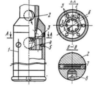
Figure 1 - Construction of kernoorientator SGI
This device contains ordinary on the construction of underbody boring shell, in overhead part of which a saddle is set 4 under a landing element as a ball 2. Round a saddle a limb is disposed 6. Line of limb
0-180 coincides with the axes of two screws 5, on the heads of which on the outward surface of колонковой pipe longitudinal lines are conducted 1 to the boring crown, thus on a line, proper a zero, there is a distinctive mark. The scale of limb is broken anticlockwise like the scale of mountain compass, that simplifies counting out of magnetic azimuth. On periphery of opening of saddle springy petals are placed 3.
A landing element is executed from material with a closeness less than 1
g/sm3 in form ball a diameter of which is a less diameter of connections of borings pipes. Through the center of ball the cylindrical opening in which the cored permanent magnet cutting-in 7 is drilled, executing the role of magnetic pointer. Athwart to the magnet on the ax of symmetry of landing element opening screw-threaded, in which a leaden load is screwed into 8, is located. Mass of lingoe must provide immersion of ball in boring solution.
Such devices allow to take away the standards of the oriented stippler without implementation of the special lowering and raising
operations, that reduces costs time. The orientation of stippler is combined with the ordinary trip of the boring drilling,
orientation is included, as a rule, in the complement of ordinary sets above pipe.
Dignity of this device is simplicity of his construction. To failings it is possible to take following:
- the knot of fixing is set in a reducer, therefore at filling of колонковой pipe a stippler the abrasion of this knot is possible;
- in a saddle for fixing of ball metallic petals are utillized.
Additional experimental works are also needed on determination of speed of turn of ball. Depending on speed of turn
of marble the depth of possible application of device will be certain.
In addition, possibility of the use for the receipt of the oriented stippler of inclinometer of MI-30 is
estimated.
Description of the developed device
A device for the receipt of the oriented stippler joins in the column of borings pipes as a muff for connection of pipes
in a candle. There is an ordinary on the composition boring shell in an underbody. Also before a shell include one or two unmagnetic
borings pipes. In the underbody of muff 2 a saddle is set 4 under a landing element as a ball 3. Round a saddle a limb is disposed.
The scale of limb is broken anticlockwise like the scale of mountain compass, that simplifies counting out of magnetic azimuth.
Into opening of saddle a rubber element is located 5 for fixing of marble.
A landing element is executed from material with a closeness less than 1
g/sm3 in form ball the diameter of which is made by 16 mm, that less diameter of connections of borings pipes. Through the
center of ball the cylindrical opening in which the cored permanent magnet cutting-in 6 is drilled, executing the role of magnetic pointer.
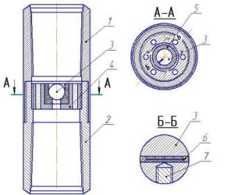
Figure 2 - The developed device
Athwart to the magnet on the ax of symmetry of landing element opening screw-threaded, in which a leaden lingoe is screwed into 7,
is located. Mass of lingoe provides immersion of ball in boring solution. On-the-spot ball the different are inflicted from each other of
half-round, proper the north and Sonth poles of magnet. An appearing meridional circumference is track of crossing of plane, passing
through the axes of magnet and lingoe, with the surface of ball. A circumference, passing through the ax of magnet, perpendicular to
the first and being an equator, is inflicted also.
Principle of action of device
For the receipt of the oriented stippler boring column with a device without a landing element put on a backwall and bore a mining hole in general a way. Before tearing away of stippler a column is drawn and through borings pipes throw down a landing element. At falling a ball is set a lingoe downward and the ax of magnet is occupied by horizontal position. Attaining lower unmagnetic borings pipes, a landing element turns under the action of magnetic-field of Earth to combination of ax of magnet with the line of magnetic meridian. Further, a landing element arrives at a saddle and fixed in it a rubber element. A stippler is torn away from a backwall and after getting up on a surface on him carry direction
0-180 with kernoorientation. Unscrewing overhead part of muff, against the line of north
read the magnetic azimuth of line, inflicted on a stippler.
Figure 3 - Principle of action of device
(animation consists of 6-ti personnels time-lagged 0,35 ms between personnels;
a delay to the repeated reproducing is 0,40 ms;
cycles of repeting: 10)
Literature
1.
Юшков А. С. Кернометрия –
М.: Недра, 1989. – 224с.
2.
Шитихин В.В. Технические средства для направленного бурения скважин
малого диаметра: Учебное пособие. – Ленинград: Недра, 1978. – 112с.
3.
Волков А. С. Буровой геологоразведочный
инструмент – М.: Недра, 1979. – 286 с.
4.
Анурьев В. И. Справочник конструктора
–машиностроителя – М.: Машиностроение, 2001. – Том 1 – 920 с.
5.
Кардашинский Л.А.,Клейман А.Ю., Пугачев В.Н. Минимизация погрешностей
передачи курса дистанционным магнитным компасом–
М.: Недра,
2003.- 240 с.
6. Нескоромных В. В., Калинин А. Г. Направленное
бурение: учебное пособие - М.: Изд. ЦентрЛитНефтеГаз, 2008. - 384 с.
7. Ганджумян Р. А. Математическая статистика в
разведочном бурении: Справочное пособие. - М.: Недра,
1990. - 218 с.
8.Пономарев П.П., Каулин В.А. Отбор керна при колонковом геологоразведочном
бурении. - М.: Недра, 1989. - 185с.
9.Гребенюк А.А. Техника и технология получения керна.
- М.: Недра, 1973. 81с.
10. Юшков А.С., Пилипец В.И. Геологоразведочное бурение.
- Д.: НОРД-ПРЕСС,
2004.
11. Иогансен К. В. Спутник буровика. [Электронныйресурс]:
http://www.npf-geofizika.ru/leuza/gti/sp_burov.htm
|
It is important! At
writing of this abstract master's work is not completed
yet. Date of final completion is
December, 1st, 2009. The complete text of work and materials on
the topic can be got for an author and scientific leader after
this date. |
|