A. V. Khludneva, M. V. Mihailov, P. A. Petrushkevich, V. V. Paslyon
Donetsk national technical university
Source of information: «Излучение и рассеяние электромагнитных волн», ИРЭМВ-2007/Материалы международной научно--практической конференции – Таганрог, Россия – 2007, стр. 61-64
The antenna systems are integral parts of modern radio aids. They are used to define the direction for the evolving source or investigating positions of many evolving sources in the ambient space. Thus, the problem of operative scanning and manipulation of the directional diagram form is one of current importance for today.
This article offers the method of electronic scanning of the directional diagrams of the reflector antennas which implies making the antenna reflector of reversing materials. The peculiarity of the reversing medium is that it is radioparent, but after experiencing the influence of the keying signal, it acquires the features of the reflective surface. That’s why our method of scanning is based on the lighting the surface of the reversing medium with the intensive light spot of the necessary size and shape. Changing this size leads to changing the width of the directional diagram and its shape in the given plane. It is obvious that the width of the directional diagram of the antenna depends on the size, shape and orientation of the light spot, e.g. it becomes narrower with the growth of the light spot. During the transference of the light spot on the surface of the reflector, we implement scanning of the directional diagram in the space. At the same time, the speed of scanning is limited only by the transmission speed of the reversing medium from the non-conducting state to the conducting, i.e. it is determined by the life time of nonequilibrium carriers of current, and by the speed of the light spot transfer; the rule of shift of the light spot disposition, as well as the directional diagram, can be arbitrary [1, 2].
Thus, this method both makes it possible to generate the directional diagram with the given form and width in the microwave range and to command the directional diagram while we are scanning, using the adjusted rule, that ensures the trajectory flexibility and the scanning high speed.
The method of scanning suggested is the base of functioning of some antenna systems such as the multibeam reflector antenna and the multibeam spherical reflector one. In these systems the changes of electrodynamic parameters of different regions of the reversing material occur with the help of the influence of command signals on the inside reflector surface, that makes possible scanning the directional diagram in the space.
The reflector of the multibeam reflector antenna is the inside surface of the rotation body of the parabolic generator around the axis that is perpendicular to the focal axis and which passes through the focus of parabola. The reflector is made of the radioparent material, but its inside surface is covered by the reversing material. The antenna system has a source of command signals. The antenna system provides the possibility of the feed elements moving along the focal axis that passes through the focus of parabola. The structural arrangement is pictured on the figure 1.
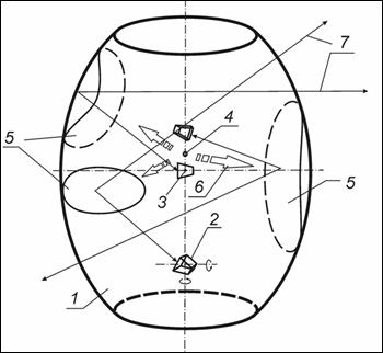
Fig.1 – The multibeam reflector antenna
The device functions in the following way. The feed elements 2 are moved along the axis that is perpendicular to the focal axis, and passes through the focus of parabola 3. The source of the command signals 4 influences on the surface of the reversing material in regions 5 with the help of signals 6 on the reflector 1. The reversing medium possesses small dark illumination in the nonexcited state that’s why the reversing medium is radioparent in this state. The intensive light spot influences on the reversing material and in these regions of the reversing surface we can observe the sudden changes of all parameters of the reversing material. They are conditioned by generating the nonequilibrium carriers of current, which change the electromagnetic characteristics of the reversing material. Thus, the reversing material acquires metallic features that makes possible to reflect electromagnetic waves. That’s why more than one ray of the directional diagram is formed.
We can change in turn the conductivity of different regions of the semi-conductor with the help of moving the spots of the command influence. As a result we have a circular scanning of the directional diagram rays in the space. The width of the directional diagram depends on size, form, and orientation of the excited regions.
Thus, the multibeam reflector antenna makes possible to form the multibeam directional diagram in the space with the circle scanning of the directional diagram rays [3].
This antenna system has some imperfections; particularly we can not make the spherical scanning of the directional diagram in the space. This imperfection is removed in the multibeam spherical reflector antenna. The reflector of this antenna is formed with the help of rotation of the circle generator. At the expense of it the geometric form of the excited region of the reflector does not depend on the direction of influence of the command signal. That makes it possible to do the spherical scanning of the directional diagram rays in the space. Moreover, we can move the feed elements round the focal center sphere [4]. The structural arrangement is pictured on the figure 2.
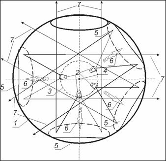
Fig. 2 – The multibeam spherical reflector antenna
The scanning method suggested is also used in the multibeam scanning antenna. This antenna system has a reflector, that is the inside surface of the rotation body of the parabolic generator around the line of symmetrization and the feed elements that are situated on the focal ring. The reflector is made of the radioparent material, but its surface is covered by the reversing material. The antenna system has the source of command signals. The antenna system provides the possibility of moving the feed elements in the focal ring plane. The structural arrangement is pictured on the figure 3.
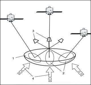
Fig. 3 – The multibeam scanning antenna
The device functions in following way. The feed elements 3 are moved in the focal ring’s plane. The source of command signals influences on the surface of the reversing material in the regions 2 with the help of signals 4 on the reflector 1.
The intensive light spot influences on the reversing material and in these regions of the reversing surface we can observe sudden changes of all parameters of the reversing material. They are conditioned by generating the nonequilibrium carriers of current, which change electromagnetic characteristics of the reversing material. Thus, the reversing material acquires the metallic features that makes possible to reflect the electromagnetic waves. That’s why more than one ray of the directional diagram is formed.
We can change in turn the conductivity of different arias of the semi-conductor with the help of moving the spots of the command influence. As a result we have scanning of the directional diagram rays in the wide sector of angles. The width of the directional diagram depends on size, form, and orientation of the excited regions. The speed of scanning is limited only by the speed of transmission of the reversing medium from the non-conducting state to the conducting one, i.e. it is determined by the life time of the nonequilibrium carriers of current, and by the speed of the light spot transfer [5].
This antenna system has some imperfections. We can not make the scanning sector wider, because the angle of the antenna aperture is constant for the reflector with a fixed diameter. Furthermore, the amplification and the width of the directional diagram are limited by the geometric size of the antenna reflector.
These imperfections are removed with the help of leading the additional parabolic reflector. The main reflector is situated in the aperture of the additional reflector. The focal center of the main reflector concurs with the focal center of the additional reflector. The inside surface of the main reflector and outside surface of the additional reflector are covered by the reversing material. Moreover, the antenna has the additional source of the command signals, which is situated on the underside of the additional parabolic reflector.
We can choose the necessary reflector and source of the command signals in accordance with the adjusted scanning sector and amplification. At the same time, another reflector is radioparent. The feed elements ensure forming more than one ray of the directional diagram. The possibility of choosing the parabolic reflector that will reflect the electromagnetic rays makes it possible to widen the scanning sector and form the directional diagram rays with a different width [6]. The structural arrangement is pictured on the figure 4.
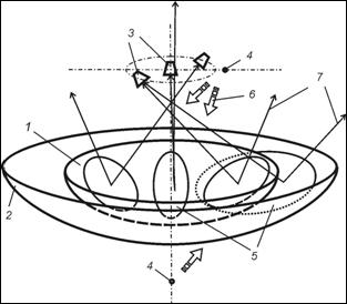
Fig. 4 – The multibeam scanning double-reflector antenna
Thus, the method of electronic scanning offered in this article has some advantages which appreciably extend the possibilities of its further use that we can see in the offered models of the antenna systems. The further development of the antenna engineering will expect increasingly fast-acting and flexible systems with expanded functions of the data handling that can ensure only electronic scanning. The result of this investigation is the offered method of electronic scanning with the help of reversing mediums which can be used in the radio engineering complexes.
References
1. Луханина О.В., Мотылев К.И., Гончаров Е.В., Хорхордин А.А., Шебанов А.О., Паслен В.В. Развитие теории и техники антенн // Матеріали ІІІ Міжнародної науково-практичної конференції “Дінаміка наукових досліджень 2004”. Том 8. Технічні науки. – Дніпропетровськ: Наука і освіта, 2004. – 26-27с.
2. Хорхордин А.А., Носко Ю.В., Паслен В.В. О возможности использования реверсивных сред в антенной технике // Міжнародна молодіжна науково-практична конференція “Людина і космос”: Збірник тез. – Дніпропетровськ: НЦАОМУ, 2004. – с. 296.
3. Деклараційний патент № 13225 Багатопроменева дзеркальна антена\ Хорхордин А. А., Паслен В. В. 15.03.06 бюл. № 3.
4. Деклараційний патент № 20355 Багатопроменева дзеркальна антена\ Михайлов М. В., Хорхордин А. А., Паслен В. В. 15.01.07 бюл. № 1.
5. Деклараційний патент № 13127 Багатопроменева дзеркальна антена\ Хорхордин А. А., Паслен В. В. 15.03.06 бюл. № 3.
6. Деклараційний патент № 20781 Багатопроменева дзеркальна скануюча антена \ Хорхордин А. А., Михайлов М. В., Паслен В. В. 15.02.07 бюл. №2.