 .
.Simulation of RFID platform on NS-2
Arini Balakrishnan, Swetha Krishnan
Источник: University of Wisconsin, Madison, December 19th, 2005.
http://pages.cs.wisc.edu/~arinib/740report.pdf
Abstract
RFID (Radio Frequency Identification) Systems have gained popularity in recent times and have found large-scale deployment in commercial and enterprise domains. However, there is a dearth of publicly available robust simulation platforms for RFID networks. The ns-2 simulation environment is a flexible tool for network engineers to investigate how various protocols perform with different configurations and topologies. This paper describes how we extended the ns-2 framework to include support for RFID systems, and illustrates their utility with an implementation of Localized Probabilistic Algorithm (LPA) used for load balancing in RFID systems.
1 Introduction
Radio frequency identification (RFID) is a general term for technology that uses radio waves to automatically identify individual items. RFID is hitting the mainstream now for a number of reasons. The recently developed electronic product code (EPC) and drive to lower tag costs are certainly a couple of the reasons. Another factor contributing to its increasing popularity is that major retailers like Wal-Mart and Tesco (in the U.K.) are mandating that all their suppliers used RFID tags on their products.
The most basic RFID system has a tag (or transponder), a reader (or interrogator) and software to control the data flowing through the system. The tag is the device that is affixed to the item being tracked and it has an integrated circuit (IC) that has all the electronics. The reader is the device that reads the information from the tag. The software transforms the data read into meaningful information. Tags can be classified as active/ passive and as read-only/read-write. Active tags are battery-driven and can reply to the reader using their own power, whereas passive tags use the energy beamed by the reader to send their reply.
RFID systems are a lot like barcodes in that both are used to identify objects. However, RFID systems are different from barcodes in many ways:
• They have no line-of-sight restrictions like barcodes.
• A single reader can read multiple items simultaneously.
• RFID tags can be used in harsh environments. RFID systems can withstand extreme heat, cold and even chemical exposure. The tag can be read through up to two inches of non-metallic debris including paint, plastic, cloth and concrete.
• Placement Flexibility.
• Speed of reading.
• Data Capacity.
• Read/Write capability
The primary purpose of this project is to establish a foundation in ns-2 for simulating RFID systems. The platform developed models the basic RFID protocol for identification of tags by readers. This work is a small contribution that should benefit RFID research where simulation is appropriate. It is an effort to aid the analysis of various RFID system configurations under the demands of specific RFID based problems like Redundant Reader Elimination (RRE)[4],schemes for RFID Privacy [5, 6] and Load Balancing Algorithms. The paper begins with an overview of the RFID EPC standards for different radio frequencies, given by MITs Auto-ID Center. Section 3 gives an overview of the ns-2 simulation environment, followed by Section 4 that describes our extensions to ns-2 and guidelines for using them in simulations. In Section 5, we describe a load-balancing algorithm that we implemented on our platform. The evaluation of our platform has been conducted through certain experiments, the results of which are given in Section 6. We conclude with a final section to list relevant areas for future extensions to this platform.
2 EPC Global Specifications for RFID
EPCglobal specifications formulated by the Auto-ID Center at MIT form the foundation for the EPC/RFID technology that the EPCglobal community has begun implementing worldwide EPC Global (www.epcglobalinc.org) has defined various classes of RFID tags .
2.1 900 MHz Class 0 Radio Frequency (RF) Identification Tag Specifications
Reference Class 0 tags are the factory-programmed tags that are used in supply-chain management applications. Class 0 tags must have the functions of: - Being factory programmed with EPC, 24 bit kill code, and optimally other data. Being read by the reader. - Being selected as part of a related group of tags, and - Being individually destroyed. The tag contains an EPC (Electronic Product Code) used for item identification, a Cyclic Redundancy Check (CRC) and a destruct code. In the EPCs so far defined there are four fields which are, in order: a version number, defining the variety of EPC among a number of possible structures; a domain manager number, which is effectively a manufacturer number; an object class, which is equivalent to a product number; and a serial number.
2.1.1 Protocol
This specification [3] uses singulation as a means to identify tags.
The term singulation refers to a process of negotiation which culminates in a single tag being selected by the interrogator for further processing via interrogator commands” [3]
To perform singulation this standard uses a binary tree walking anti-collision protocol where the reader initiates the singulation. There may be contention i.e. simultaneous replies from multiple tags yet this does not result in a loss of information. The reasons for this behavior are as follows. Firstly, the bits 0 and 1 are encoded with two different sub-carrier frequencies. Hence, the reader can simultaneously receive a zero and one. Also, it is not important that the reader receiving multiple zeros (or multiple ones) should be able to distinguish one zero (or one) from the other. This is evident from the way tree-walking works as described in Section 4. Secondly, destructive interference between tag replies of equal strength is very unlikely and can only be intermittent. This can be attributed to the changes in the reader-tag carrier frequency and drift in the internal tag sub-carrier tones.
|
ЕРС TYPE |
HEADER SIZE |
FIRST BITS |
DOMAIN MANAGER |
OBJECT CLASS |
SERIAL NUMBER |
TOTAL |
|
64 bit type I |
2 |
01 |
21 |
17 |
24 |
64 |
|
64 bit type II |
2 |
10 |
15 |
13 |
34 |
64 |
|
64 bit type III |
2 |
11 |
26 |
13 |
23 |
64 |
|
96 bit and more |
8 |
00 |
28 |
24 |
36 |
64 |
Table 1: Four varieties of EPC code
2.1.2 Communication channel specification
The reader-to-tag communication is carried out by an AM pulse-width modulation of the reader-transmitter carrier, operating at 900 MHz. The tag (passive) replies to the reader using the energy of the readers beam, by the method of modulated RF Backscatter. Modulated backscatter requires no transmission power and is achieved by alternately changing the chip port impedance and thus the reflectivity of the tag antenna. The backscatter can result in either of two frequencies -2.2 MHz and 3.3 MHz - which are the tag sub-carrier tones for 0 and 1 respectively. Thus, all communications happen through three reader-to-tag symbols (data 0, data 1 and a null symbol ) and two tag-to-reader tones(0 and 1).
Due to FCC requirements, the reader is required to change its frequency of operation periodically (every 50 to 400 milliseconds), by the process of Frequency Hopping. The new frequency jumped to is within 1 MHz of the earlier frequency. However, no assumptions can be made that the tags will remain powered after a frequency hop and so such tags which temporarily go out of power shall be negotiated only through subsequent frequency hops.
If allowed according to the jurisdictions of the region, Direct Sequence Spread Spectrum technology can also be exploited by the reader and tags. Using this broadband direct spreading method, the reader is not required to hop through frequencies, thereby overcoming the tag power loss issues caused by moving to a different frequency.
2.1.3 Tag Identification Numbers
According to this specification [3], each tag is associated with three ID numbers, ID0, ID1 and ID2. ID2 (with a total length of 80/112 bits) is the one that contains the actual user EPC data (version, domain manager, product class and serial number), which is of 64 or 96 bits, followed by a 16-bit CRC calculated using all the bits of the EPC data.
Singulation if carried out using ID2 becomes inefficient and expensive as it would require the tag to send out and the reader to keep track of all the 64 or 96 bits of the EPC data. However there may actually be only about 1000 tags in the system and so a 12-bit number used for singulation will easily suffice to distinctly identify each of those tags. Also, sending out bits of EPC data may pose security issues.
To avoid using ID2 for the above stated reasons, the tag is provided with two other IDs ID1 and ID0, which are used in singulation by negotiating a minimum number of random bits. ID1 is a static pseudo random number that is generated from a seed based in ID2s CRC. It consists of 64 bits thus generated, plus 16 interspersed parity bits, thus giving a total of 80 bits (one parity bit for every 4 bit). ID1 is required to be the same for every singulation of tag, irrespective of the reader that is querying the tag and irrespective of the environments the tag is in. ID0 is a fully randomized dynamically generated number that changes each time a tree traversal process begins (or even while in midst of one). It is used when very a high level of security is desired.
ID1 and ID0 are divided into 10-bit blocks to facilitate singulation. The idea behind this is to use lesser number of bits than the complete ID2 to ease singulation. However, considering the fact that the reader does not know how many tags there are in the system prior to singulation, it is not possible to decide upon a fixed number of bits to use out of the 80 bits of these 2 IDs. Instead, the singulation is carried out at the granularity of a block (10 bits) and depending upon the readers requirement to isolate each tag to uniqueness, the reader decides how many blocks will be used. Each block is always read completely (10 bits) by the reader. But after reading a block, the reader may or may not go further to another block depending upon whether it is able to differentiate between the tags currently in the system.
2.2 13.56 MHz ISM Band Class 1 Radio Frequency Identification Tag Interface specification
The EPC structure of this specification is similar to that of the 900 MHz specification. The differences between the specifications are in the frequency of operation and the protocol used. The 900MHz (UHF) specification uses tree-walking algorithm that has frequent and brief periods of communication between the tag and the reader. In such types of communication the number of tags read per second depends on the turn around time. Since at UHF, large bandwidths are available very less turn around times can be achieved. This is not the case in the 13.56 MHz (HF) specification where the bandwidths are significantly less and the turn around times are high. Hence, this specification [1] describes a different algorithm for the basic operation.
2.2.1 Slotted Terminating Adaptive Collection Protocol (STAC)
STAC is a reader-initiated protocol. STAC protocol has some notion of rounds which is explained below. In STAC, tags reply at random positions or time intervals referred to as slots. A collection of such slots form a reply round. The reader initiates the protocol by sending a Begin Round message which has a number of parameters like the number of slots in the forthcoming round, a selection that selects the labels which will participate in the round and a hash value which are used to generated random reply positions in the round, using the tag memory contents. Also, within each round and among rounds the tags occupy random positions, so collisions between replies are neither frequent nor repeated. The selection parameter of the Begin Round message when present represents the number of bits and the bits to be compared with the EPC in the selection process. If the selection parameter is not present then all the tags in the readers vicinity will be selected. The Begin Round causes the tags to set the round size parameter, the selected or not selected bit and a reply slot position. It also sets counter of reply slot positions to zero. Also the tags move from READY state to SLOTTED READ state, in which state the tags calculate for themselves a proposed slot and wait until the slot counter reaches the proposed slot calculated. The slot counter will increment every time a reader indicates the end of the slot and the beginning of a new slot. The tag replies with the remaining bits in its EPC omitting all or most of the bits which were in the selection parameter. The reply conditions of the slot can be any one of the following
1. no tag reply present
2. one tag reply present
3. two or more replies present
If the reader detects that no tag reply is present then it issues a Close slot sequence that causes all the tags in the SLOTTED READ state to increment their slot number. If the reader detects that one / more of the tags are replying it will try to keep the slot open for a time sufficient for the reply/replies to conclude and be evaluated. The reader checks the CRC present in the reply, against an expected value that may be calculated from information present in reader to tag and tag to reader signaling. If these checks reveal that the data is not collected properly, the reader sends a Close Slot sequence to the tag and the tag returns to the READY state. If the label is collected correctly the slot is closed by giving a Fix Slot command. The tag upon receiving this command moves from SLOTTED READ state to the FIXED SLOT state, in which state the tag continues to reply once per round, but always in the fixed slot.
2.2.2 Communication Channel specification
The reader carrier frequency falls within 13.56 MHz and ± 7 Khz. The tag receives its power, and instructions which regulate its behavior from the interrogator. The baud rate in the reader to tag link is 26.48 kbit/sec (fc/512) The tag reply is generated though amplitude modulation of the oscillation in the tuned circuit containing the tag antenna coil, wherein the tuned circuit load is switched by sub-carrier frequency fs. The frequency of the sub carrier, fs is fc/32(423,75kHz). The tag reply data of 0 is coded with 4 pulses of fc/32( 423,75 kHz) sub-carrier, followed by an un-modulated time of 128/fc( 9.94us). The tag reply of data 1 starts with an um-modulated time of 128/fc(-9.94us) followed by 4 pulses of fc/32( 423,75kHz) sub-carrier. The baud rate in the tag-to-reader link is 52.969 kbit/s (fc/256).
2.3 860MHz – 930 MHz Class 1 Radio Frequency (RF) Identification Tags
The class 1 tag in this specification [2] is designed to communicate only with its unique identifier.
The reader carrier frequency is in the range of 860 MHz 930 Mhz. The The tag replies with backscatter modulation. The tags will modulate their back scatter only when they receive a command from a reader, which they can properly decode and interpret. The intended free space communication of a tag is more than 3m . It is 2m in worst case and 10m in best case. The tag contents of the class 1 tags are slightly different from class 0 tags in that these tags have a short password in addition to the EPC and CRC. Password is a 8 bit string used by the kill command.
3 Overview of NS-2 environment
The NS-2 environment [7, 8] provides support for mobile wireless nodes using the 802.11 specification. It also includes support for node movements and energy constraints. In the NS-2 environment RFID systems can be built with the same set of protocols and characteristics as those available in the real world. To implement an RFID system in NS-2 environment would require the following modifications:
1. The physical layer should be modeled in such a way that nodes that are tags do not have power of their own.
2. The MAC layer should be modeled to support RFID systems. The changes here would include, disabling RTS/CTS, disabling SIFS/DIFS and disabling the congestion window mechanism to avoid delays.
3. Adding agents to model the tags and readers
4. Modifying the appropriate files in NS-2 to support the changes made.
4 Extended NS-2 Architecture
One fundamental aspect of RFID systems, which is missing in NS-2 is the protocol for singulation of tags by readers.

Figure 1: Singulation Tree
We implemented the tree-walking singulation protocol as described in [6]. A RFID reader is able to communicate with only one tag at a time. If multiple tags reply to a request from the reader, the reader detects collision and in this case the RFID tags and reader should engage in some sort of protocol so that a reader can communicate with conflicting tags one at a time. The tree-walking protocol is a negotiation between the readers and the tags in the system, which allows the reader to identify all the tags in its range singly. The tree-walking algorithm is a bit-by-bit depth first search performed by the reader in the following way:
• Starting at a subtree at depth d the reader queries all the tags in the system with the prefix 6061 • • • b2bd.
• The queried tags reply with the d + 1st bit if the prefix matches with the prefix queried by the reader. A tag broadcasts ’0’ if it is in the left subtree of the singulation tree or a ’1’ if it is in the right subtree.
• If there are tags both in the left and right subtree of the tree, both 1 and 0 is transmitted resulting in a collision.
• When the reader B detects collision, the reader recurses beginning at its child node B\\0 and Б||1. The reader starts its query from the root of the singulation tree. An example of a singulation tree for 3 bits is shown below
4.1 Modeling Tags and readers
We modeled tags and readers as agents. Agents represent the endpoints in NS-2 where the network layer packets are consumed or constructed and used in the implementation of protocols in various layers. We developed two agents: a Reader agent, to model the RFID reader; and a tag agent, to model the RFID tags. Reader Agent is modeled like a class that inherits from the Agent class. The reader agent class has the following members: A reader ID A set of tags A vector of events A Reader Timer class that inherits from Timer Handler and is a friend to the Reader Agent. Tag Agent is modeled like a class that inherits from the Agent class. The tag agent class has the following members: A tag ID A Singulation ID A set to hold reader information. The singulation protocol is implemented in the NS-2 environment using reader agents and tag agents. The singulation implementation works as below: 1. Reader agent starts the singulation by broadcasting a 0 and schedules this event with the Reader Timer. 2. In the mean time the reader receives replies from the tags. 3. When a reader receives a ’0’ from a tag it inserts the event of broadcasting the prefix in the left sub-tree to the vector of events 4. When a reader receives a ’1’ from a tag it inserts the event of broadcasting the prefix in the right sub-tree to the vector of events. 5. When the reader receives both ’1’ and ’0’ in the scheduled time, it inserts the prefix in both the left and right sub-tree to the vector of events. 6. When the timer expires the control reaches the expire function of the reader timer which in turn calls the tree walk function with the event in the top of the vector. 7. Also to enable this broadcast by the readers we set the destination address to IP_BROADCAST and ttl() to ’1’ in the message sent by the reader. On the tag agent side, 1. When a tag agent receives a singulation packet, it compares its Singulation ID with the prefix received and if it matches, the tag replies with the next bit in the Singulation ID. 2. If the prefix received does not match its singulation ID, then the tag does not reply. We
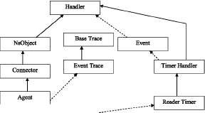
Figure 2: Collaboration diagram for Reader Agent class
also created new packet headers for RFID reader and RFID tag packets. The packet headers contain a field type which is used to identify the type of packet being sent. We used three different packet types in our system:
1. Singulation packets with packet type 100
2. LPA packets with packet type 101
3. Query packets with packet type 102.
The use of LPA and query packets will be detailed in the Section 5. Colloboration diagram for ReaderAgent class is shown in Figure 2
4.2 Files Modified
In addition to this, we needed to make modifications to various existing files in ns-2, as follows:
1. trace/cmu-trace.cc,h: The CMUTrace class is used to print important parts of a packet to the simulations trace file, for wireless simulations. Since we introduced new packet types for the Reader and the Tag, we had to describe the corresponding packet format in this class. In the CMUTrace::format() function, we added cases to handle the 2 new packet types PT_RFIDREADER and PT_RFIDTAG , whereby the format_msg() function is invoked just as in the case of PT_MESSAGE packet type.
2. common/packet.h: This file contains all the functions related to packets allocate, free packets, access the packet at a particular offset etc. Each packet in ns-2 is associated with a unique type that associates it with the protocol that it belongs to, such as TCP, ARP, AODV, FTP, etc. Since we created a new RFID Protocol, we defined its corresponding packet types in the packet.h header file. The packet.t enumeration list of this file was modified to include PT_RFIDREADER and PT_RFIDTAG also, and the Enumeration constants to-Name mappings defined in the p_info class were enhanced to include the mapping for PT_RFIDREADER and PT_RFIDTAG
3. tcl/lib/ns-default.tcl: This file contains Otcl commands to set the default values for the various parameters of Tcl Objects. We incorporated the setting of the packet.size parameter for the the two new Agents we created - ReaderAgent and the TagAgent - to the default values of 1000 and 64.
4. tcl/lib/ns-packet.tcl: This tcl file contains commands and procedures dealing with creating and accessing of packet headers. We added references to our new protocol types RFIDREADER and RFIDTAG here so as to be able to add and manage packet headers for all packets of these protocols.
4.3 Features Incorporated in the TCL script used for simulations
1. Disabling of Wireless routing- The RFID Protocol involves direct communication between readers and tags and so does not require routing of any form since any packet will travel only one hop, from reader to tag or vice-versa. Hence, in the node configurations in our TCL script, we set the routing agent to Dumb Agent which is an agent that simply passes packets between the node attached to it and the source; it does no forwarding of packets.
2. Disabling of RTS/CTS Mechansims in 802.11 Mac layer : Since ns-2 uses 802.11 mac layer for wireless nodes, that is the underlying Mac layer we have used, however many mechanisms of this mac are not a part of the RFID protocol. Hence, we disabled the RTS/CTS handshake mechasnim of 802.11 by setting the RTSThreshold to a high value of ’3000’ in the tcl script. This is done because, in ns-2, an RTS/CTS exchange will be performed only if the size of the packet is larger than RTSThreshold, so setting this threshold to a very high value, bigger than the size of packets in our protocol, will ensure that RTS/CTS exchange is disabled.
3. Also the transmission range of the reader can be changed by setting different values to RXThresh_. RXThresh. is used to set the RXThreshold or the receiver threshold. If the power level of the packet arriving at a node is less than RXThreshold, the node will receive the packet with error. This RX-Thresh. value can also be used to set the transmission range of the reader. To determine the RXThresh. for a particular transmission range, we used the program /indep-utils/propagation/threshold.cc.
7 Future Work
The simulation platform we have implemented is a basic platform that models the tags and readers in a RFID system. We have used the NS-2 wireless nodes and attached the tags and readers as agents to those nodes. But NS-2 wireless nodes work on mac-802.11 which is different from the way the RFID systems operate. One of our future works includes simulating the MAC layer behavior on NS-2. This would include modifying the mac/mac802-11.cc,h files to disable the congestion window mechanism. The other relevant mac changes like disabling RTS/CTS and disabling DIFS/SIFS could be done from the Tcl scripts itself. Also the physical layer characteristics of mobile nodes are different from that of the RFID readers and tags. Our next step would be to modify the physical layer provided by NS-2 to reflect the physical layer of RFID system. This would necessitate modifications in the Phy/WirelessPhy.cc,h that would model a tag as a node with no operating power.
References
[1] 13.56 mhz ism band class 1 radio frequency identification tag interface specification: Candidate recommendation, version 1.0.0. http://www.epcglobalinc.org/standards.technology/Secure /v1.0/HF-class1.pdf, February 2003.
[2] 860 mhz - 930 mhz class 1 radio frequency identification tag radio frequency and logical communication interface specification candidate recommendation,version 1.0.1.
http://www.epcglobalinc.org/standards.technology/Secure /v1.0/UHF-Class1.pdf, November 2002.
[3] 900 mhz class 0 rfid tag specification.
http://www.epcglobalinc.org/standards.technology/Secure /v1.0/UHF-class0.pdf, February 2003.
[4] B. Carbunar, M. K. Ramanathan, M. Koyuturk, C. Hoffmann, and A. Grama. Redundant reader elimination in rfid systems. 2005. CERIAS TR 2005-63.
[5] A. Juels and J. Brainard. Soft blocking: Flexible blocker tags on the cheap. In S. De Capitani di Vimer-