Introduction
Synchronous Digital Hierarchy (SDH) is a set of international standards for broadband communications over single mode fibre optic transmission systems. It uses a transfer mode which defines the switching and multiplexing aspects of a transmission protocol and supports both asynchronous and synchronous traffic in any form. The standards were originally developed in the US, where they are known as SONET (Synchronous Optical Network).
A Network-to-Network Interface (NNI) was specified by the CCITT to enable national and regional networks to be blended into a cohesive global network. It describes the characteristics of a fibre optic physical infrastructure (OSI Layer 1), rather than a set of services. Recently developed services, such as Frame Relay, ATM and B-ISDN, which depend on the availability of bandwidth, good error performance, flexibility and scalability, can best be provided over an SDH infrastructure. B
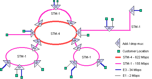
asic signal levels of E1 (2 Mbps) and E3 (34 Mbps) can be multiplexed into an STM-1 or STM-4 signal. The SDH signal, being synchronous, allows direct access to all of the component signals without the need to de-multiplex the complete signal. Thus, only sufficient equipment to add or remove the required signal are needed at any location. Typical SDH Network Typical SDH network equipment includes:
• Add / Drop Multiplexer: allows the insertion (add) or removal (drop) of the required bandwidth from an SDH signal passing through the multiplexer.
• Terminate unit: similar to an add / drop multiplexer but designed to terminate an SDH signal.
• Digital Cross Connect: provides switching and circuit grooming down to an E1 level and can provide a link between STM signals of different levels, eg between an STM-4 and an STM-1 signal.
• Repeater: amplifies and re-times the SDH signal. SDH networks are usually configured to be highly redundant, with dual fibres providing backup.
They can be laid out in a linear fashion, however, the optimum network topology is a ring. In a ring configuration, the first fibre transmits in one direction, with the second fibre transmitting in the opposite direction. Through this layout, it is highly unlikely that any device on the network can be isolated through a catastrophic failure. This feature is known as "self healing". T
ypical network configurations usually include a number of intersecting SDH rings, with the lower levels (STM-1 or 4) being used for access and the higher levels (STM-4 or 16) being used for the backbone network. Other configurations are becoming more widely used to meet specific needs, particularly the need to easily connect additional add / drop mux equipment, particularly for customer connections.
Typical SDH Network
A network will also include a Telecommunications Management Network (TMN) which will allow the monitoring of the performance of the network, detection and analysis of faults, and the setting up and clearing down of links between customer locations.
Network Planning
In addition to the obvious planning activities of locating optical fibre routes in proximity to likely sources of business and dimensioning the capacity of the individual routes, consideration must be given to the siting of equipment. An optical budget must be determined, which may be impacted on to some extent by the choice of equipment. Geographical diversity of the routes is also a consideration in developing a resilient network. In addition to the traffic network, other networks must be designed and built. These include the synchronisation network, the management network and the alarm network. Implementation A
s in any network, installing the infrastructure is only the first step. A comprehensive testing regime is required, starting with the optical fibre. As each piece of equipment is added and tested, it is integrated into the network, allowing a higher level of testing to be carried out. Retention of test results is essential so that subsequent in service testing results can be compared with the original results and deterioration noted and, where necessary, remedied.