1 Introduction
2 Experimental Device
3 Results
4 Discussion
5 Conclusions
References
An original experimental device is used to reproduce conditions of orthogonal cutting for a wide range of cutting speeds (from 15 to about 100 m/s) (Sutter et al.). Improvement of the initial device (Sutter et al.) makes it possible to record both values of normal and tangential forces in orthogonal cutting. An analysis of the tool–chip friction is then possible for a large range of cutting speeds. The evolution of cutting force components as well as the evolution of the friction coefficient are presented and analyzed. In addition, the process of chip formation during high speed machining is illustrated by photographic recording with a high speed camera.
Keywords: HIGH SPEED MASHINING, CUTTING FORCES, ORTHOGONAL CUTTING, FRICTION
1 Introduction
The complex phenomenon of cutting is the subject of numerous theoretical and experimental studies. The evolution of technologies tends to increase continuously the cutting speeds and the performance of material properties. Thus there is a strong need for experimental analyses of high speed cutting processes. In this article an experimental setup, originally developed in [1] is used to analyze orthogonal cutting. Orthogonal cutting is defined by Merchant [2] when the cutting tool generates a plane surface parallel to an original plane surface of the material being cut and is set with its cutting edge perpendicular to the direction of relative motion of tool and workpiece. These conditions are rarely found in industrial processes — because in general several cutting edges are involved (particularly in milling) and cutting edge directions are oblique -, however, these simplifications permit the analysis and understanding of phenomena.
The present device allows experiments to be performed without some of the constraints found in conventional machining tests. Therefore, it is possible to investigate a range of speeds from 15 to 100 m/s by keeping the device very rigid and limiting parasite vibrations. Furthermore, the good accessibility ensures a perfect visualization of the cutting process. Numerous studies have been published concerning experimental devices in high speed machining [3 — 8], but they are limited either by the speed of cutting, or by the measurement of a single component of acting forces.
Improvement of the existing setup [1], allows now measuring the two force components in orthogonal cutting. The first results obtained on medium carbon steel (42Cr Mo4) are presented here. Photograph recordings during the chip formation illustrate the evolution of the chip’s morphology with the cutting speed.
2 Experimental Device
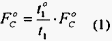
The main characteristics of the modified device [1] are presented here. The modifications are made to allow measurements of the thrust component of the cutting force together with the longitudinal component. Figure 1 shows a simplified schematic description. These measurements give an estimation of the value of the friction coefficient at the tool-chip interface. An important characteristic of the experimental setup is its high rigidity. Consequently, the obtained cutting conditions remain precisely orthogonal and quasi-stationary after a short transient period.
Measurement of the thrust force component, FT , is made possible by a new design of the tool holding fixture. Figure 2 shows details of the tool holding fixture located at the entry of the transmitter tube. Two tools are symmetrically disposed on the tool holding so as to permit simultaneous machining on both sides of the workpiece specimen. A projectile launched by an air gun carries the specimen. Each tool is fixed on a beam with a sufficient section to insure high rigidity. Cutting forces subject the beams to compression and bending solicitations. Strains are measured on each beam with gauges placed at two different locations. The components of the cutting forces in the directions parallel and normal to the cutting direction can be deduced from strain measurements.
Measurements are obtained on the right and left tools. A precise positioning of tools and specimen is assured so as to be as close as possible to symmetric cutting. The specimen geometry is meticulously measured before and after every test to determine the depths of cut for each side. The difference in the depth of cut due to the small positioning default is taken into account by a correction of the value of the forces, see [1]. Let us remember that the launched tube is designed to assure a precision of 0.015 mm in the lateral position of the projectile.
However, a little difference in the depth of cut is observed between tools. This is due partly to a symmetry defect in the position of the specimen on the projectile of the order of 0.02 mm and to the precision of the guidance of the projectile. Therefore, the possible variation of the depths of cut for each tool is in the order of 0.05 mm. This small disparity between the real cutting depth t1 and the theoretical value t1o (for a perfect symmetric test) is corrected in the following way. Denoting by FC , the measured cutting force in the cutting direction (Fig. 4), the cutting force FCo associated to FTo is evaluated as:
The same correction is made for the transverse component of the force FT (normal to the cutting direction, see Fig. 4). In that way, considering the reference depth of cut to, small deviations with respect to to are corrected as in (1) and the forces reported in this paper are FCo and FTo . The supports of tools have strong sections to limit the flexion that could modify too much the expected depth of cut t0.
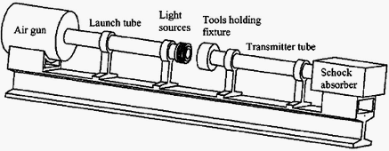
Fig. 1 — Schematic description of the experimental setup
The workpiece carried by the projectile is a rectangular parallelepiped with a length L parallel to the cutting direction (Fig. 2), a width w, and a height h. All the tests have been carried out with carbide tools (type: SCMT 12 04 08-UR 235), a new one being used for each shoot. These tools were of square shape without chip-breaker. All the tests presented here have been performed with a rake angle having a value of zero, two depths of cut to = 0.2 and 0.5 mm, and a length L = 12 mm.
The calibration of the device, in other words the relation between the signal intensities obtained and the cutting force components, is made in two ways. First, by static test where the loads are imposed on the cutting tool with a hydraulic machine and then by finite element calculations. These two calibrations are confirmed by results already obtained from the previous setup, see [1]. The mass of the projectile is calibrated in order to have a kinetic energy large enough with respect to the mechanical work necessary to perform the cutting operation. Thus the cutting velocity is nearly constant during the process and quasi-stationary cutting conditions are realized. In that purpose it is worthwhile using projectiles with the same geometry but different mass densities (steel, aluminum, polymer). Speed and acceleration of the projectile are measured from a set of three sources of light, photo-diodes and time counters near the process cut zone. The light beams located at the end of the launch tube detect the passing-by of the projectile. The possible range of velocity is from 15 to 100 m/s.
To complete the range of cutting speeds, similar tests were made on an NC lathe with the same tools and for cutting speeds going from 0.5 to 20 m/s. This NC lathe is equipped with a dynamometer KISTLER 9265B which allows two components of the forces to raise (cf. Fig. 3). To obtain cutting conditions close to the orthogonal cutting process a circular piece with an important diameter (125 mm) is machined on this lathe. The significant diameter makes it possible to neglect the effect of the curvature of the machined surface. Before testing grooves are machined on the piece.
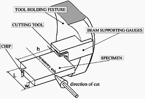
Fig. 2 — Details of the tool holding fixture
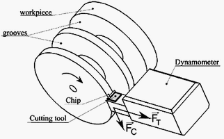
Fig. 3 — Cutting device on numerically controlled lathe
A high speed camera is located near the zone of manufacturing. The phenomenon duration time to be filmed requires a very short exposure time (of the order of a few microseconds) so a significant luminous intensity is needed, which is assured by two flashes of high power. This requires a perfect synchronization of the trigger mechanism with the photographic recording system.
3 Results
Experiments have been driven on a medium carbon steel (42CrMo4) with chemical composition specified in Table 1. Figure 4 presents the different components of acting forces developed in the process.
nbsp;nbsp;nbsp;nbsp;
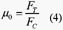
Let us assume that all useful forces to chip production act only on the tool rake face. The mean coefficient of friction ![]() , between the tool and the workpiece is defined by the ratio of the cutting forces RT and RN acting on the tool and obtained as follows:
, between the tool and the workpiece is defined by the ratio of the cutting forces RT and RN acting on the tool and obtained as follows:
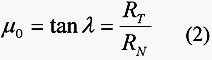
where ![]() is the friction angle. Considering that:
is the friction angle. Considering that:
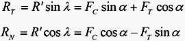
the relationship (2) can be written as:
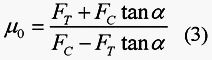
so, for a rake angle ![]() = 0°, the friction coefficient can be obtained directly by the measurement of the cutting forces:
= 0°, the friction coefficient can be obtained directly by the measurement of the cutting forces:
However, in metal cutting, intimate contact occurs between the work material and the cutting tool. This contact extends from the tool rake face to the tool nose region. As a consequence, the forces coming from the third zone (located near the cutting edge, cf. Fig. 4) may be taken into account to determine a real friction coefficient ![]() at the tool-chip interface [9]. In fact the measured resulting forces are the sum of the cutting and parasitic forces. These parasitic forces include in a large part edge forces depending on the tool nose geometry because the cutting tool has a defined cutting
at the tool-chip interface [9]. In fact the measured resulting forces are the sum of the cutting and parasitic forces. These parasitic forces include in a large part edge forces depending on the tool nose geometry because the cutting tool has a defined cutting
Table 1 Chemical composition of the 42CrMo4 steel

edge roundness greater than zero. Additional forces due to the built-up formation and tool wear mechanism are neglected as all tests are short-lived and use a new cutting tool. It is supposed to be identical for each test. For the lower cutting
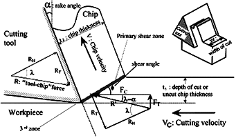
Fig. 4 — Different forces in orthogonal cutting process
speeds corresponding to the longest durations of cut, the tools are examined by an interferometric microscope. Except for light marks on the tool rake face, no change was observed on the profile of the tool. Similarly results are obtained at a high cutting speed (around 40 m/s). These edge forces do not depend on the chip thickness. Experiments showed that even for a very small chip thickness there is cutting force. Parasitic forces are identified by a linear regression of the cutting forces according to the chip thickness at constant speed [9]. The magnitude of these residual forces is read by extrapolating down to zero chip thickness. This approach is an approximation to evaluate the evolution of the friction. Thus, the longitudinal cutting force FCt and the transverse cutting force FTt which act on the tool rake face are:
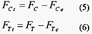
where FC and FT are the longitudinal and transverse cutting forces measured experimentally and FCe and FTe are the edges forces. Finally the real friction coefficient ![]() at the tool–chip interface is given by:
at the tool–chip interface is given by:
A typical oscillogram obtained from the strain gauges setup located on each tool support is presented in Fig. 5. This measurement corresponds to a cutting velocity of VC = 22.5 m/s and for t1 = 0.2 mm. The recording is commanded by the impact of the workpiece on tools. Four signals correspond, respectively, to the recording of the gauges situated on the tool holders. Gauges 1 and 3 as well as gauges 2 and 4 are similarly localized on each beam supporting the tools. When the test is symmetric these signals are similar two for two and present each a plateau having a duration
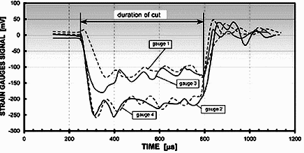
Fig. 5 — Oscillograms from strain gauges located near the tools
corresponding to the machining length of 10.5 mm. This length of cut corresponds to the almost constant part of the signal without the peak due to the dynamic load. These plateaus characterize the longitudinal cutting force FC and confirm the stationary process conditions.
The various oscillations result from the flexibility of the support tools and fixations as well as from reflections of loading waves. The symmetry of the cutting process creates this similarity by a pair of signals. The strains recorded by the gauges result from the superimposing of a load in flexion and in compression on beams supporting the tools. The load of compression imposed by the transverse component FT of the cutting force reduced the signal amplitude for gauges 1 and 3.
To maintain similar conditions on the NC lathe to those obtained with the air gun setup, the measurements were made during the second revolution of the workpiece. Indeed during the first revolution on the lathe, the uncut chip thickness increases as the tool approaches the cylindrical workpiece. Later this uncut chip thickness keeps a constant value. The higher duration of the cut on the lathe before measuring corresponds to the lower cutting speed and reached 0.8 s. With the air gun setup the maximum duration is about 8 ms.
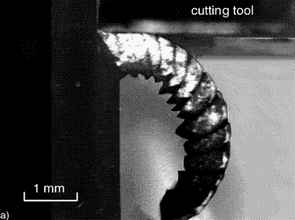
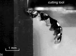
Figure 6 presents two real-time photographs of the chip formation during the cut (the depth of cut is 0.5 mm for the two cases). This picture has been taken with 1 ms of exposure time. On this picture we observe that the cutting tool surface remains perpendicular to the relative motion of the workpiece during the process.
 |
 |
|---|---|
Fig. 6 — Real time photographs of chip formation for two cutting speeds VC.
(a.) VC = 15 m/s; (b.) VC = 45 m/s
4 Discussion
The duration of each test on the NC lathe or on the ballistic setup has been less than one second. For these conditions there was no built-up edge to be liable for incurring an increase of the cutting forces. The dispersion of the results may be attributed to the different sharpnesses of the tool tip or size margins after each tool change. For the two depths of cut considered and for the low velocities up to 15 or 20 m/s, the measured cutting forces FC and FT decrease with increasing cutting speed (see Figs. 7 and 8) until a minimum value.
This evolution is directly related to the decrease of friction at the tool-chip interface due to the increasing temperature at this interface when the cutting speed is increased. This result confirms the Mathews and Oxley’s [10] analyses, which consider that the temperature sensitivity of the material is more important than the strain rate sensitivity. The same results were found by Findley and Reed [8].
For velocity higher than 15 m/s, the cutting forces have an inverse evolution. The inertial forces can be estimated using a basic dynamics approach suggested by Bredendick [11]:
where ![]() is the workpiece material density. The normal component of the inertial forces RiN (normal to the rake face) acting on the tool is expressed by:
is the workpiece material density. The normal component of the inertial forces RiN (normal to the rake face) acting on the tool is expressed by:
So, for a rake angle ![]() = 0°, the inertial forces can be simply written:
= 0°, the inertial forces can be simply written:
The inertial forces at a cutting speed of VC = 40 m/s (for t1 = 0,2 mm) normal to the rake face are RiN = 25 N, which is about 0.5% of the measured value of FC = 5000 N. Therefore, the inertial forces take a weak part in the force increase given Figs.7 and 8.
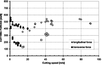
Fig. 7 — Longitudinal ( FC ) and transverse ( FT ) cutting forces as a function of the cutting speed for medium carbon steel (42CrMo4), width of cut w = 10 mm, depth of cut t1 = 0,2 mm, rake angle  = 0°. (
  : NC lathe;
  : Air gun setup)
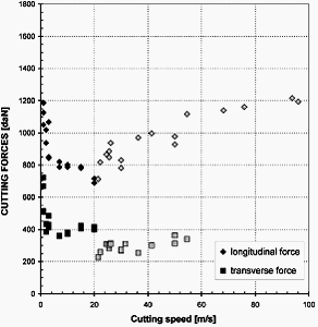
Fig. 8 — Longitudinal ( FC ) and transverse ( FT ) cutting forces as a function of the cutting speed for medium carbon steel (42CrMo4), width of cut w = 10 mm, depth of cut t1 = 0,5 mm, rake angle = 0°. ( : NC lathe; : Air gun setup)
Komanduri et al. [7] have previously observed this thin influence at around 50 m/s.
A possible reason for the increase of the force could be the large strain-rate sensitivity observed in steels at very high strain rates. This was also found by Klocke [12] for high speed turning of steel and aluminum. Old results obtained by Salomon [13] predicted a critical cutting speed for which a maximum cutting temperature is reached. More recently, Recht [14] has presented a similar evolution of the cutting pressure for a 4340 steel, with a minimum value at around 35 m/s.
In addition, Fig. 6 corroborates that the smallest cutting force is located above VC = 15 m/s, because the length of the chip segment tends to increase for VC = 45 m/s. Indeed, the minimum cutting force seems to correspond to a minimum length of the chip segment [15].
To analyze the cutting forces, FCt and FTt acting on the tool rake face, Eqs. (5) and (6) are used with the edge forces previously defined and presented in Fig. 9. For the cutting speed range from 0.5 to 55 m/s, they can vary from 180 to 210 daN (or 1800 — 2100 N) for the longitudinal component (FCe ) and from 90 to 200 daN for the transverse component (FTe ). In addition, the evolution of the parasitic forces versus cutting speed presents a similar evolution for the transverse cutting forces and opposite for the longitudinal cutting forces. The corrected force level for different depth of cut confirms also that the cutting forces are in direct proportion to t1 . This feature is illustrated in Fig.10, where the ratio ![]() of the normalized corrected cutting forces (associated to the values t1 = 0.2 mm and t1 = 0.5 mm) is shown in terms of the cutting velocity. The normalized cutting forces
of the normalized corrected cutting forces (associated to the values t1 = 0.2 mm and t1 = 0.5 mm) is shown in terms of the cutting velocity. The normalized cutting forces
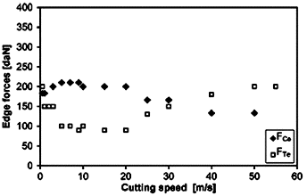
Fig. 9 — Effect of the cutting speed on the longitudinal FCe and the transverse FTe edge forces
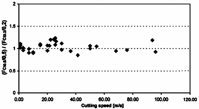
Fig. 10 — The ratio  as a function of the cutting speed for medium carbon steel (42CrMo4), width of cut w = 10 mm, rake angle
  = 0°
= 0°
are defined as being corrected longitudinal cutting forces divided by the uncut chip thickness t1 . These results are coherent with the Merchant approach, where the ratio ![]() is equal to unity, because the normalized forces are not depending upon t1 .
is equal to unity, because the normalized forces are not depending upon t1 .
A particularity of the present experimental device is that it allows, as dynamometers, the deduction of the friction coefficient evolution between the tool and the chip. Using the abovementioned Eq. (7), the evolution of ![]() is drawn on Fig.11. The broken lines plotted in Fig. 11 show only a tendency. For both depths of cut, the friction coefficient decreases with the increasing speed to reach a minimum value. Findley and Reed [8] for leadantimony alloy (
is drawn on Fig.11. The broken lines plotted in Fig. 11 show only a tendency. For both depths of cut, the friction coefficient decreases with the increasing speed to reach a minimum value. Findley and Reed [8] for leadantimony alloy ( ![]()
![]() 0.85 at VC
0.85 at VC ![]() 0, to 0.3 at 13 m/s), and Tanaka et al. [16] for steel observe this large decreasing (
0, to 0.3 at 13 m/s), and Tanaka et al. [16] for steel observe this large decreasing ( ![]()
![]() 0.6 at VC
0.6 at VC ![]() 0, to 0.18 at 133 m/s) and confirm that this coefficient
0, to 0.18 at 133 m/s) and confirm that this coefficient ![]() decreases as the depth of cut increases. For 4340 steel, Recht [14] explains the drop in
decreases as the depth of cut increases. For 4340 steel, Recht [14] explains the drop in ![]() from 0.6 at 4 m/s to 0.26 at 36 m/s as being due to melting at the asperities. Similar results are obtained by
from 0.6 at 4 m/s to 0.26 at 36 m/s as being due to melting at the asperities. Similar results are obtained by
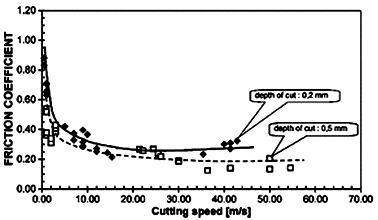
Fig. 11 — Experimental evolution of friction coefficient at the tool-chip interface for a wide range of cutting speeds
Montgomery [17] for a steel — steel friction at sliding speeds up to 550 m/s. For a cutting speed higher than 25 m/s we have to notice a slight rise of this coefficient for the lowest depth of cut.
5 Conclusions
Results presented in this work show the capabilities of the air gun setup, which can be used for orthogonal machining in a large range of cutting velocities (from 15 to 100 m/s). A new tool holding system has been designed, allowing to record the two components FC and FT of the cutting force. The first results confirm the existence of a critical cutting speed (about 15 — 25 m/s) for which the minimum forces for medium carbon steel (42Cr Mo4) are reached. A minimum has been found for the tool-chip friction coefficient at about 25 m/s for the lowest depth of cut. On the other hand, the conception of this device makes it possible to record photographs in real time with one microsecond exposure. The quality of these records allows carrying on our attempts to describe the chip formation in detail over a wide range of cutting speeds.
References
[1] Sutter, G., Molinari, A., Faure, L., Klepaczko, J. R., and Dudzinski, D., 1998, "An Experimental Study of High Speed Orthogonal Cutting", ASME J. Manuf. Sci. Eng., 120, pp. 169 — 172.
[2] Merchant, E., 1945, "Mechanics of the Metal Cutting Process. I. Orthogonal Cutting and a Type 2 Chip", J. Appl. Phys., 16(5), pp. 267 — 324.
[3] Kottenstette, J. P., and Recht, R. F., 1982, "Ultra-High-Speed Machining Experiments", Proceedings, Ninth North American Manufacturing Research Conference, Trans. ASME, pp. 263 — 270.
[4] Hoffmeister, H. W., Gente, A., and Weber, T. H., 1999, "Chip Formation at Titanium Alloys under Cutting Speed of up to 100 m/s", 2nd International Conference on High Speed Machining, edited by Schulz, H., Molinari, A., Dudzinski, D., PTW Darmstadt University, pp. 21 — 28.
[5] Lee, D., 1985, "The Effect of Cutting Speed on Chip Formation under Orthogonal Machining", Int. J. Eng. Industry, 107, pp. 55 — 63.
[6] Hastings, W. F., Mathews, P., and Oxley, P. L. B., 1980, "A Machining Theory For Predicting Chip Geometry, Cutting Forces etc. from Material Properties and Cutting Conditions", Proc. R. Soc. London, Ser. A, 371, pp. 569 - 587.
[7] Komanduri, R., Flom, D. G., and Lee, M., 1984, "High Speed Machining", edited by Komanduri, R., Subramanian, K., and Von Turkovich, B. F., ASME, pp. 15 — 36.
[8] Findley, W. N., and Reed, R. M., 1963, "The Influence of Extreme Speeds and Rake Angles in Metal Cutting", ASME J. Eng. Ind., 85(2), pp. 49 — 67.
[9] Wallace, P. W., and Boothroyd, G., 1964, "Tool Forces and Tool–Chip Friction in Orthogonal Machining", J. Mech. Eng. Sci., 6(1), pp. 74 — 87.
[10] Mathew, P., and Oxley, P. L. B., 1982, "Predicting the Effects of Very High Cutting Speeds on Cutting Forces, etc.", CIRP Ann., 31(1), pp. 49 — 52.
[11] Bredendick F., 1959, Die Massenkrafte beim Zerspanvorgang. Werkstatt und Betrieb, Jahrg. 92, Heft 10, Carl Hanser Verlag, Munchen, pp. 739 — 742.
[12] Klocke, F., Raedt, H.-W., and Hoppe, S., 2001, "2d-FEM simulation of the orthogonal high speed cutting process", Mach. Sci. Technol., 5(3), pp. 323 — 340.
[13] Salomon, C. J., 1931, "Process for the Machining of Metals of Similarly — Acting Materials When Being Worked by Cutting Tools", German Patent No 523594.
[14] Recht, R. F., 1984, "A Dynamic Analysis of High Speed Machining", High Speed Machining, edited by Komanduri, R. et al., ASME, New York, pp. 83 — 93.
[15] Sutter, G., Faure, L., Molinari, A., Delime, A., and Dudzinski, D., 1997, "Experimental Analysis of Cutting Process and Chip Formation at High Speed Machining", J. Phys. IV, 7, pp. C3 — 33 — C3 — 38.
[16] Tanaka, Y., Tsuwa, H., and Kitano, M., 1967, "Cutting Mechanism in Ultra-High-Speed Machining", Trans. ASME, paper No 67 — PROD — 14.
[17] Montgomery, R. S., 1976, "Friction and Wear at High Sliding Speeds", Wear, 36, pp. 275 — 298.