
Objectives
Using mathematical models of different frequency converters based on the package MatLab a comparative analysis of the transient regimes of BP when feeding on different HR.Tasks
To achieve this goal it is necessary to solve the following tasks:1) Consider the various power circuits with a link inverter DC.
2) Conduct a simulation of transient regimes in BP when feeding on different HR
3) Conduct a comparative analysis of the results obtained with BP on FPGAs and IF with the DC link
4) To consider the theoretical aspects of construction and the range of FPGAs.
5) Develop a mathematical model of the power of BP NHR
6) Consider the option of feeding BP matrix inverter
The novelty and practical value
Theoretical results will be used in teaching the course "Elements of automated electric." Mathematical models presented in the paper will form the basis for creating the cycle of laboratory studies on the power inverter circuits.
The structure and volume of work
The work consists of: entry, 3 sections, conclusions and lists of sources used. In its introduction, the actuality of the problem being addressed, formed the main target areas of the study, as well as the results for the defense [5].
I. Section
The analysis of the stages of creating the drive with dc link
The first stage is characterized by the development of mass production and industrial use, the most simple IF performed on a "controlled thyristor rectifier - LC Filter - Autonomous thyristor voltage inverter with artificial commutation.
The first models had odnokomplektny controlled rectifier, which did not allow to exploit the energy network in the brake of the motor. Subsequent modifications included the use of IF dvuhkomplektnogo controlled rectifier for realization of the recovery. Are more advanced schemes of forced commutation autonomous inverter, realizing mode 180 0 control with improved form of the output voltage.
Together with the drive based on voltage inverter developed inverter with inverter current. A significant advantage of such converters is the possibility of recovery mode using odnokomplektnogo controlled rectifier [8].
The main disadvantage of such converters is Nonsinusoid output current and the unevenness of the motor at low frequencies, which limits the range of speed regulation, speed limits, due to the presence of power filters in the channel amplitude control the size of output voltage. Nonsinusoid current consumed from the network and low "network" power factor, due to the properties of controlled rectifier with a natural commutation and phase control
Drawing 1
The second stage is characterized by the development of new two-tier semiconductor converters, made on a "unmanageable hair straightener - LC Filter - thyristor or transistor autonomous inverter with pulse-width modulated output voltage (fig.3.2.)
The control system includes three-phase leading generator SH harmonic vibrations and high-frequency oscillator sawtooth voltage scanner GPN. The frequency and amplitude of the second harmonic voltage is given from the potentiometer or from SU EP. Each harmonic voltage is summed with the SH deploying voltage GPN and fed to the zero-body NO. The alternating voltage, which are obtained at the output of a zero-makers, managers power valves, usually transistors, through the mind. The output voltage follows the bipolar voltage nulling, but has great size and power. The front should be delayed.
Drawing 2
Here at the expense of more complex algorithm switching power switches on the inverter tasked with regulating not only the frequency but the amplitude of the fundamental harmonic voltage at the converter output at a constant voltage to the DC link. The transition from the pulse-amplitude to pulse-width method of forming and regulating the output voltage substantially changed the properties of IF. It is as follows.
Substantially closer to the sinusoidal shape of the output current and consequently improved the uniformity of rotation of the engine, expanded the range of speed regulation.
Significantly improve the performance of electric, because power filter at the output of an unregulated rectifier is effectively excluded from channel to regulating the output voltage of the converter.
Substantially improved power factor converter as a consumer of energy.
However, the shortcomings of such converters is the lack of elaboration of some of the issues of energy saving, quality of electricity and electromagnetic compatibility of transducers.
The third stage is characterized by the decision of these deficiencies on the basis of use, in a part of DC rectifiers with forced commutation, called active rectifiers. In the power circuit of such converters consistently included active rectifier voltage "APD", filter F and autonomous voltage inverter AES. Power semiconductor switching elements of the rectifier and inverter, have complete control, and bilateral conduction current, conventionally shown as a key. Rectifier is made of three-phase bridge circuit converts the voltage of the mains alternating current into a stable DC voltage U d on the capacitor filter. Three-phase bridge AES operates on a pulse-width modulation "PWM" and converts this DC voltage to AC voltage at the output with the desired values of frequency and amplitude of the fundamental harmonic. This provides a favorable form of motor current and the uniformity of its rotation in a wide range of speeds.
Active rectifier is essentially a call AES also operates in PWM mode.
How to switch the current active rectifier converts the consumption of the AC, which is close to sinusoidal, the current in the pulsating output current, containing a variable and constant components. The variable component is closed through the buffer capacitor, which limits the ripple voltage U d in the DC link of the variable component of output current APD. Note that this capacitor performs the same role with respect to the variable component of the current consumed by self-contained two-link inverter transformer. The constant component of the output current APD fueling buffer capacitor to compensate for consumption of the DC given out in the input circuit of AES.
As a power converter dc to ac power inverter has a self-contained extremely valuable quality - the possibility of bilateral power exchange between networks of direct and alternating current. This property is maintained in the inverted scheme the inclusion of autonomous inverter as an active rectifier. As a result, the drive with an active rectifier provides two-way energy exchange between the supply chain and the engine, including modes of energy recovery in the supply chain
II. Section
Based on the analysis, the mathematical model of AD with CP when feeding on different power sources (network, an ideal inverter, inverter with PWM). One of these mathematical models is shown in the figure.
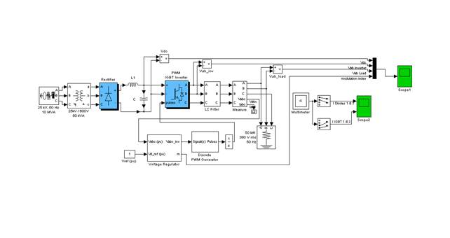
Drawing 3. Model with PWM inverter in the package MatLab.
The results simulation made it possible to compare transients in BP and to evaluate them.
III. Section
The analysis of existing schemes for RAMs and given them to score. The result showed that high-speed electric with FPGA is only possible when using a fully managed Semiconductor key that is made in the creation of a matrix inverter.
Drawing 4*. The scheme of the matrix inverter.
* – Figure animated(6 cycles; 4 cycles of repetitions done in Gif Animator; 150 kb)
* – To view the animation from beginning you must update page
Have been developed mathematical models of AD with CP rotor with a matrix inverter and obtain the diagram of transition regimes. The figures show: a mathematical model of the matrix IF and simulation results.
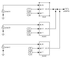
Drawing 5- Model of the matrix phase inverter
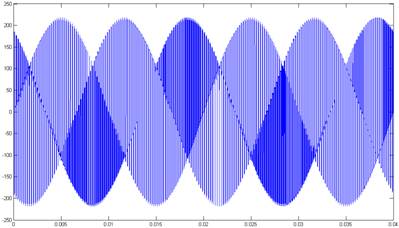
Drawing 6- The curve of output voltage inverter for f o = 100 Hz
Findings
Mathematical models are used in the laboratory the following courses: "Electronics" and "Elements of automated electric.
The results simulation inverter with DC link, showed that the use of PWM inverter with IGBT transistors in the current appears in the form of a large amplitude of the third harmonic compared to the 2-level approach to the PWM inverter.
Research NHR showed their potential as an energy source for the AC motor.
Theoretically, the questions considered in this paper will be used for reading course: "Electronics" and "Elements of automated electric.
At present essay is not yet completed, the results of studies and abstracts itself will be completed in December.
REFERENCES
1. Руденко В.С.,Сенько В.И.«Преобразовательная техника». – Киев, «Вища школа», 1979г.
2. Бернштейн И.Я., «Преобразователи частоты без звена постоянного тока». – М. 1968г.
3. Забродин Ю.С., «Промышленная электроника». – М. Высш. школа, 1982. – 496с.
4. Дьяконов В.П. «MATLAB 5.0/5.3. Системы символьной математики», Москва, «Нолидж», 1999г.
5. Масандилов Л.Б., Анисимов В.А., Горнов А.О, Крикунчик Г.А., Москаленко В.В. «Опыт
разработки и примененя асинхронных электроприводов с тиристорнымми преобразователями напряжения», Электротехника №2, 2000г.
6. Бернштейн И.Я. Тиристорные преобразователи частоты без
звена постоянного тока –М.:Энергия, 1968,–88с.
7. Бизиков В.А., Обухов С.Г., Чаплыгин Е.Е. Управление непосредственными преобразователями частоты.
8.Электрические машины : учеб. пособие для студ. высш. учеб. заведений
Беспалов В.Я. , Котеленец Н.Ф.– М. : Издательский центр «Академия», 2006. – 320 с.
9.Автоматизированный электропривод типовых производственных механизмов и технологических комплексов: Учебник для вузо
в Белов М.П., Новиков В.А., Рассудов Л.Н.– 2-е изд., стер – М. : Издательский центр «Академия», 2004. – 576 с.
10.Инженеринг электроприводов и систем автоматизации : учеб. пособие для студ. высш. учеб. заведений Белов М.П., Зементов О.И., Козярук А.Е.и др. ; под ред. Новикова В.А. ,Чернигова Л.М.. – М. : Издательский центр «Академия», 2006. – 368 с.