Introduction
Energy Program for the long term provides for further development of the EEC. Commissioning of large power plants, intensive development of basic and distribution networks extremely complicate the management problem.
In this regard, there is a continuous process of development and improvement of technology of relay protection. Create and entering into service new protection for large generators, transformers and power units. Develop new types of semiconductor differential-phase defenses, which are easier and safer to operate.
Relay Protection is a main type of electrical automation, without which reliable operation of modern power systems. It provides continuous monitoring of the condition and mode of operation of all elements of power and responds to the appearance of lesions and abnormal regimes.
The main requirements imposed to the relay protection:
Selectivity
Fast action
Sensitivity
Reliability[1]
Topical issue
Currently evolving digital technologies that are being introduced in the sphere of human activity. Because energy is one of the major industries, the modernization of its technical base is a priority and is very intense.
This development of technology requires skillfully trained personnel to work with the new equipment. In this connection there is need for a university teaching model.
Communication with scientific themes, plans and programs
Qualifying work of the master performed during 2009-2010. in accordance with the scientific direction of the Department of Electric Power Stations of the Donetsk National Technical University.
The purpose and objectives of development and research
Objective
Since the main power in our country produce a turbo-generators and their protection are paramount. In this regard, there is need to develop a simulation program of the protection unit generator-transformer capacity of 300 MW.
The idea of work
Creating a suitable model for teaching students and the possibility of visual presentation of the work and interaction of various relay protection unit.
The main objectives of development
Development of educational software.
Subject of development
Development is performed using the software package Microsoft Visual C + +.
Project of development
Scheme circuits control current protection unit generator-transformer capacity of 300 MW.
Methods and techniques of development
The paper uses methods of logical construction of relay protection.
Scientific novelty
Scientific novelty of this paper is that the developed software system is one of the first developments in this direction at the Department of Electric Power Stations
The practical significance of the results
This development will better prepare future professionals in the field of relay protection, as well as give them an opportunity to review and correct their mistakes.
Approbation of the work results
Report on the theme of "Modeling of the logical part relay-type protection of the block generator-transformer by power 300 MW" presented at the conference to the "Science Day-2010" DonNTU Department of Electrical stations.Donetsk, DonNTU-2010.
Also was done a report on the Odessa Internet conference in 2010.
Review of research and development
National Review
For information on the trainer "Corwin-3.
The general procedure for constructing models of RE and PA.
While the primary wiring devices are in the simulator graphical representation, wiring devices and the secondary status of secondary devices do not have the graphical representation. They are generally described in the database and displayed on the screen in the form of tables - the attributes and protection status. Each device has its primary attribute table and states associated relay protection.
Circuit voltage, current and operational chain of each security may be in the position of "inclusive" or "disabled". Each protection and breaker failure of her launch may be in the position of "put" or "you-Vedeno. Various types of secondary devices may also have other selectable attributes of states.
Changing the attributes of the secondary device is user-like editing fields pi-lits attributes of protection by selecting a field value from a list of possible values. Attributes (columns) Oto-brazhaemoy tables have one of two types of access: either "read only" or "read and modified. For example, the name of the type of protection only displayed and can not be changed, and the state protection available for change.
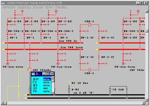
Figure 1 - Displaying and switching attributes relay protection during training
Formation of model systems of relay protection and automatic (RH and PA, or secondary devices) in the database simulator CORVIN-3 is carried out in the program "Design patterns" function "RH and PA. In the model of RE and PA enables you to define virtually all types of relay protection and breaker failure, APV, ABP and automatic.
When choosing the main menu item, the designer of schemes, the RE and PA "drop-down menu:
Locks
Protection
APV
ABP
Speakers Sync.
Fixed boards Master-switches.
Transformers
Generation
Formation model of the secondary devices is carried out in two stages. First performed automatically-agency development kits RH and PA by default. This is done by a team of "Generation" dan-tion menu. Then generated sets of secondary devices are adjusted in a dialogue with other teams in this menu.
Generation RZA
Generation of RPA, ie automatically generate sets of relay devices, carries out the construction of a database of models following types of devices RZA:
primary and backup relay protection
CBFP
APV
ABP
When generating a relay for each of the primary device is constructed maximum logically possible set of devices, RZA, from which to choose is actually installed in a model of types of devices. For each transmission line is formed by a logical set of all possible main and backup protection of lines:
differential (DZL)
Differential Phase (DFZ)
directional differential (NDZ)
radial differential (RDL)
transverse differential (PDZL)
remote (RS)
digger (ZZ)
Overcurrent (DOLE)
current cut-off (TO)
maximum phase cutoff (MFI)
The records of all these defenses are placed in the database, and all these protection are considered as possible WIDE. As the real one is automatically set one primary - DFZ and one backup - the DMZ. This protection is valid by default. For transformers automatically generates maximum logically possible set of primary and backup protection:
differential (DZT)
gas (GBs)
remote (RS)
digger (ZZ)
current cut-off (TO)
As the actual arguments are two main - DZT and GBs, and two back - the DMZ and that. For sections of tires formed a defense - DZSH and established as real. Similar way formed sets relay for generators and switches.
For each relay program autopartition finds that voltage transformer, which fed voltage circuit of this protection (if it is drawn in the scheme of primary connections),. For example, circuit voltage relay protection transmission line or power transformer joins the "closest" to the topology of circuit voltage transformer. "Nearest" Th is sought first to join transmission lines (power transformer), and if the accession of the protected equipment in the scheme no Th, then Th is found in Section tires, to which it is attached equipment. If the bus is not TN (scheme), the circuit voltage of the relay is considered uncertain in the model of RPA. In this case, it is not involved in the operations of its state and state transitions are not controlled.
The current and operating protection circuits join in the generation of models relay all the switches which are of direct surrounding protected equipment. For each "next" switch-tion connected to the power circuit (both closed and open) to the protected equipment is determined by the accession of the current and the operational chain of relay protection. If the power circuit is closed, then for the current and operational chains set the initial state of "inclusive". If the power circuit is open, then for the current and operational chains set the initial state "disabled".
Start CBFP (device redundancy switch-out) from the protection of equipment is determined by all the switches, which are connected to the operational chain of protection. If the power circuit protected equipment maintenance with the switch is closed, breaker failure protection is installed in the state of "inclusive". If the power circuit-protection schaemogo equipment with a switch is open, CBFP installed in the state of "disabled". Logs-ka tripping breaker failure: if the defense was unable to turn off a switch, and if you have entered the action CBFP for this switch, the breaker failure will try to turn off all breakers adjacent to the data you-klyuchatelem all closed power circuits.
On the power lines and power transformers installed three-phase device APV (automatic repeat-tion included) - TAPV. In addition, the single-phase power lines are installed APV - OAPV. The section of tires be linked APVSH.
Operating circuit recloser device equipment attached to all the switches adjacent to the data components from a logistical on all power circuits. If the power circuit is closed, the effect of APV on the switch is introduced. If the power circuit is open, the effect of APV on the switch is removed-nym.
The device Arnt (automatic voltage regulation transformer) that is installed on every power transformer, in the initial state is defined as enabled. Communication devices Arnt with other circuit components are not introduced.
At the sectional switches installed device AVR (Automatic power reserve). The section on tires installed switch lock violation accessions.
In addition, the execution of the "Generation RZA" in the database are defined:
lock disconnectors and earthing switches with
speakers sync to the switch
knife to commit violations of sections of the tire fixed connections
Adjustment RZA
Logic circuits of the secondary devices formed in a database program for their generation, are the schemes by default. If the training set of them is redundant XML, too many devices or you can remove the connection - transfer to a state of "invalid".
After generating the model RH and PA user browses automatically created sets of real and possible secondary devices, and adjusts these sets in accordance with reality or the requirements of the educational process. Adjustment is possible that elements of the RE and the PA can be translated into the category of real, as real - as a possible. To do this, the user calls up a list of all the secondary elements are automatically defined for the selected first in the scheme of the primary device. In this list against each element of the RE and PA given its status avail-being - "is" this item or "no". Changing the status to the opposite by pressing the Spacebar. Thus, the effort required for the construction of the model RH and PA minimized.
Displayed during training and are involved in only the secondary device, which "is". The device, which "is" may be in a position or "put" or "withdrawn". Pe-tus of secondary devices trainees change their state "entered" / "withdrawn", but do not change the status of the availability of "be"
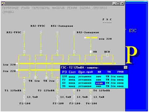
Figure 2 - Adjustment sets RZA
Global Review
The model of protection is intended primarily for use in the simulator to simulate the routine switching effects of a power of reaction to emergency situations arising as the initial conditions of anti-accident training, either because of trainee's erroneous actions. The reaction model is usually represented a power user in the form of circuit breaker, loss of Blinker, scoreboard and lights on the electronic layout.
If you have any dangerous situation the main task - turn off the damaged area to locate the damage.
Interestingly, the security model is generated automatically based on analysis of a topology of a power circuit. This creates lists of sites protection schemes (co-sponding power facilities - substations on the network map), zones of protection, and deadlocks.
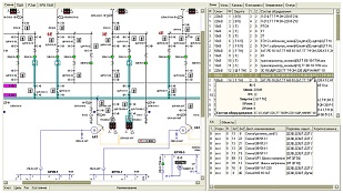
Figure 3-List of protections zones
Thus, in order to enhance security model in the simulator, dos only takes properly prepare a power scheme in the graphical editor.
Automatically generates a set of protection devices, which monitor the status of network elements and operating parameters. Their mission - to detect violations and when they occur off the damaged section by controlling the impact on certain switches. For zones, dial switch, creates a predefined set of protection devices and control components, characteristic of the machines in this class tension.
The list of device models and cases of their application is listed in the table: The elements of protection and automation in the software complex Modus
Name of the device Equipment Description
DZSH Systems Section tires 6kV and above, with more than two accessions from all types of short circuit in the protected zone, including switches. No sensitivity to external Indeed KZ.Po default if not defined controls output circuits, modeled part time scheme with controlled-lems of the current flow in the short-circuit to disconnect accession.
DZSHT Systems Section tires 110kV and above, with more than two accessions backup protection, similar DZSH. The model works if the main protection removed. Can be used for simulation of breaker failure in the CP to join.
APVSH Systems Section tires 110kV and above, with more than two accessions model automatic reclosing tires. Starts to work following only after the appointment of officials to operate the unit in section "Management".
Provides secondary school setting under stress from a line to the control voltage presence. If successful, the scheme collects control matching.
HRT transformers 10kV and above transformer off from all sides in the coil short circuit.
DZT Transformers 110kV and higher off the transformer from all sides in any kind of short-circuit in the tank, except the coil
DZOSH Transformers 110 kV and above transformer off on all sides with any kind of short circuit on the oshi-lation of the relevant class napryazheniya.V if DZT collected on current transformers circuit breakers, it is recommended as the government used the same as for DZT tank.
KIV Transformers 330 kV and above model of the device isolation control inputs of the transformer. On-cludes a transformer on all sides if damaged insulation. Equipped with the transformer 220 kV and above.
DFZ cable and overhead transmission lines 110kV and above the main line of defense against all types of short circuit. Creating the standalone kit for each knot security line. Each set is switched off em line with his hand.
APV Air and Cable-air lines over 0,4 kV model automatic reclosing of lines. Begins to work only after the appointment of authorities to operate the unit in the "management". Assigned to areas that are in the area of air lines.
Carries placing under tension lines to the control tension on the tires. In case of success, closes with the transit control matching.
OAPV, TAPV Air lines 330 kV and above set of single-phase automatic reclosing the line and three-phase automatic reclosing circuit breakers.
In fact a single-phase short circuit is simulated work OAPV. In other cases - TAPV.
RS air, cable and cable-air if-ing, transformers svy Hsi 35kV backup protection from phase to phase short circuit. For each node is formed by one set for each element of the band performed with the following drawing primitives:
liaison with the object, if tip_linii installed air or cable;
vozdushnaya_liniya;
kabelnaya_liniya;
transformer.
Multiple sets can simulate the work of the various stages, since each set of controls damage to the only appropriate site.
TZNP Similarly DMZ backup protection from short circuit to earth. Terms of configuration are the same as in the DMZ.
IFHT Similarly CLE backup protection from phase to phase short circuit. Terms of configuration are the same as in the DMZ.
MTW Switches to 35 kV simulated overcurrent protection or current-cutoff ki.Dlya each switch creates two devices (one for each of the adjacent areas), mimic the direction of protection. Cpa-earns some of the devices for which the current CP is directed to obscure the protected zone.
ABP, ZMN switches and machines 110kV and below the simulated input automatically reserve. The current version has the following types of ABP:
backup power from adjacent sections
Reservation of lines (AVRL)
ZMN off the opening switch on the fact of the absence of tension and lets ABP control voltage presence. ABP Induction is blocked when disconnecting switch of protection zones.
In the software package Modus protection devices are differentiated by type of CP: protecting sensitive to short-circuit to the ground, to interphase short circuit, and universal protection, sensitive to any type of CP.
In addition, the protection system performs automatic operations on the rehabilitation of power supply, hence the protective devices, the program provides par excel-lence Automation - Automatic re-enabling the line (once) and automatically enters the standby power from another source.
When you use the simulator for operational switching is necessary to ensure the implementation of learner modeling operations with protection and automation. In practice, working with them seems dispatcher as an interaction with a set of panels, indicator, signal lights (display elements), as well as linings and circuit breakers (controls), which is part of an interactive model of protection. Therefore, protection system provides the ability to set correspondence between the protection device and its controls and display, represented in the layout.
Each device is modeled in part:
A sensory organ that contains the controls and display, presented by the section "Management».
Output circuits on the number of controlled switches, containing control and indication provided by the "Step".
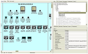
Figure 4-Windows configuration management body par protection
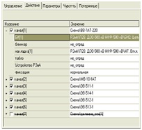
Figure 5- Window channel settings Action protection device
The model generates a model set of protection devices for protection, but he can race with the real-hoditsya used at a power plant. To eliminate this nedos-Tutka Playing Animator there is great potential donastroyki set protection devices manually. It is possible to add the missing device is determined by the applicable laws of type, block unused, configure the zone of sensitivity, add or remove channels of action, change the sequence of operation by setting the holding time, etc. Most of these features fine-tuning is implemented in the fifth version of the software.
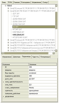
Figure 6-The window settings of protection
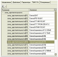
Figure 7- Window settings zone sensitivity
The main content of work
Among the many protection and automation unit to select bases-WIDE, for their simulation. According to the SEP for the generator-transformer units with generators of 300 MW shall be provided to re-lane protection against these types of injuries and abnormal operating modes:
1) earth fault on the side of the generator voltage;
2) multi-phase circuits in the generator stator winding and its findings;
3) circuit between the turns of one phase in the stator winding turbogenera-torus;
4) multi-phase circuits in the windings and the findings of the transformer;
5) single-phase earth fault in the winding of the transformer and its you-waters attached to the network with high earth fault currents;
6) circuit between turns in the windings of the transformer;
7) External short circuit;
8) overload the generator currents reverse;
9) symmetrical overload of generator stator winding and winding transformers,;
10) overload of the generator rotor winding current excitation (for turbo-generators with direct cooling of winding wires and hydro generators);
11) increase the voltage on the stator of the generator and transformer unit;
12) earth fault at one point the drive circuit;
13) asynchronous mode with the loss of excitation;
14) lowering the level of oil in the tank of the transformer;
After the data entry program examines the type and location of damage, and then selects and executes the required function of the program. As a result, will be made simulation of protection.
Figure 9 - Diferrent relay types, which uses in protection
(Animation: volume-208 КБ; size- 208 КБ; number of shots- 6; delay between shots- 2000 ms; number of repetion cycles- infinity)
CONCLUSION
The final output of the work are as follows:
The analysis of technological problems relay energoblo-ka 300 MW;
A simplified block diagram of the proposed program;
In the future includes the development of application software ensure the simulation of the logical part of the relay unit of 300 MW.
References
1. http://student.km.ru/ref_show_frame.asp?id=6EFF3A6BCAD64F03AB180A26EB311E68
На сайте представленно большое количество рефератов.
2. http://masters.donntu.ru/2002/eltf/oleynikov/diss/index.htm
Описание программы "Корвин-3".
3. http://www.swman.ru/content/blogcategory/82/119/
Краткий обзор программы "Модус".
4. ПРАВИЛА УСТРОЙСТВА ЭЛЕКТРОУСТАНОВОК ШЕСТОЕ ИЗДАНИЕ, ДОПОЛНЕННОЕ С ИСПРАВЛЕНИЯМИ. М.: ГОСЭНЕРГОНАДЗОР, 2000
5. Лихачёв Ф.А. Замыкания на землю в сетях с изолированной нейтралью и компенсацией ёмкосных токов.-М.,”Энергия“ ,1971.151с.
Сирота И.М.,Кисленко С.Н. и др. Режимы нейтрали электрических сетей.”Наукова думка“,1985.264с
6. Усов С.В., Кантан В.В., Кизеветтер Е.Н. Электричкеская часть электростанций,М-Л.,Энергия,1972,558с.
7. Данилович М.С.,Пославский М.О.Комутационные перенапряжения привключении и выключении высоковольтных электродвигателей, “Электрические станции”,1973,№1,с.68-70.
8. Черников А.А. Компенсация емкостнвх токов в сетях с незаземленной нейтралью. М., “Энергия” 1974. 96с.
At writing of the given abstract a master’s work has not been finished yet. Date of the work’s final end is on December, 1st, 2009. Full text of work and materials on a theme can be received from the author or her supervisor after the named date. |