Source of information: http://www.selinc.com/WorkArea/DownloadAsset.aspx?id=3538
The era of protecting rotating equipment using electromechanical devices has faded away. Today’s motor
protection is accomplished with digital protective relays. Digital relays are multiphase, multifunction units that offer
not only protection but also alarming, historical operational data, and communication to other microprocessor-based
devices in a plant.
The most important facet in motor protection is the ability to accurately replicate heat flow into and out of a
motor.
This paper discusses the dual first order thermal model and its superior ability to protect ac motors from
overtemperature conditions during starting and running states.
Digital relays are multiphase, multifunction microprocessor-based devices. With proper mechanical and electrical design precautions, these relays offer highly reliable and advanced protection of power system components. Any past protection limitations experienced in the world of electromechanical relays are no longer a factor. If a situation can be mathematically described, the microprocessor in a digital relay can be programmed to tackle that problem. Because of the immense computing power of today’s microprocessors, digital relays offer additional, highly important features to complement protection. They alarm, store historical operating data about the protected equipment and the power system it is connected to, and communicate to other microprocessors in the plant, using a large selection of communications protocols. Digital relays are also miniature programmable logic controllers (PLCs). Relay protective elements, digital inputs, digital outputs, and analog quantities can be used in logic statements, generating custom control schemes to suit specific applications. Digital relays are no longer standalone protective devices. They can be incorporated into the overall manufacturing process in a plant.
The world of motor protection presents unique challenges. The most prominent challenge is modeling of motor temperature based on electrical current flow.
This paper discusses the dual first order thermal model, which is based on the thermodynamic laws of heat flow.
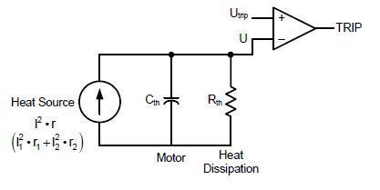
FIGURE 1 illustrates the first order thermal model. The major components of the model are:
Heat source. Heat flow from the source, I2r, is measured in watts (W).
Thermal capacitance, Cth, which represents a motor with a thermal capacity to absorb heat from the heat source. The unit of thermal capacitance is W • s/C.
Thermal resistance, Rth, which represents the heat dissipated by a motor to its surroundings. The unit of thermal resistance is C/W.
Temperature, U. The unit of temperature is °C.
Comparator, which compares the calculated motor temperature with a pre-set value based on the motor manufacturer’s data.
The qualitative analysis of this model states that heat produced by the heat source is transferred to the motor, which in turn dissipates the heat to the surrounding environment.
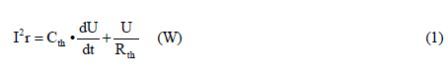
The quantitative analysis is defined by a first order linear differential equation, similar to a parallel resistorcapacitor (RC) electrical circuit:
Motors comprise two major electrical components, stator and rotor. The stator produces a rotating magnetic field (at line frequency) in the air gap, inducing voltage in the rotor bars. This induced voltage produces current flow in the rotor bars. Rotor current produces a magnetic field of its own. The rotor magnetic field is at 90 degrees to the air-gap magnetic field, thus generating torque tangential to the rotor surface, resulting in rotational force, thus turning the shaft. Because the construction of the stator and rotor is dissimilar, so are their thermal characteristics. To accommodate the difference in stator and rotor thermal properties, two separate thermal models are used to achieve greater accuracy:
1) Rotor model
a. Starting element – protects the rotor during the starting sequence.
b. Running element – protects the rotor when the motor is up to speed and running.<.p>
2) Stator model – protects the stator during starting and running.
Transition from one rotor element to the other occurs at 2.5 times the rated full-load current of the motor.
APPLYING FIRST ORDER THERMAL MODEL TO MOTOR STARTING
Starting an ac motor is considered an adiabatic (lossless) process.
Starting deposits a large amount of heat (magnitudes greater than rated heating) in the rotor bars. Also, the duration of the starting sequence is magnitudes shorter than motor thermal time constants. Thus, it is regarded that any heat deposited in the rotor will not dissipate to the surroundings during the starting sequence. It will dissipate later when the motor is up to speed and running, and air flows in the air gap.
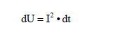
Applying this assumption to the first order thermal model depicted in FIGURE 1, we are effectively stating that the thermal resistance of the rotor during starting is infinity (R = ?). Substituting this condition into (1) yields
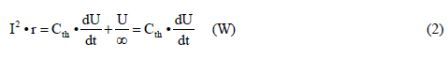
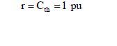
The thermal capacity of a motor is a physical attribute and does not change. Motor resistance is assumed to be constant at this point. Convert the above expression to per-unit (pu) quantity by substituting the following:
Thus:
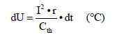
Integrating the expression:
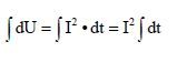
The solution to this general integral is
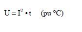
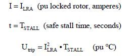
Motor manufacturers supply thermal limit information as part of motor data. The starting thermal limit is expressed in terms of the maximum time (motor safe stall time) that corresponding locked-rotor current can be applied to a motor. Applying this to (3):
Incorporating the above into FIGURE 1 results in a rotor I2t starting element in FIGURE 2
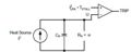
FIGURE 2. Rotor I2t Starting Element
Plotting the pu temperature response of this model versus the line current of the motor, the response curve is a straight line, as illustrated in FIGURE 3.
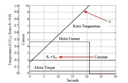
This model keeps the rotor resistance constant at RM, which occurs at standstill (S = 1.0) and is considered 1 pu. HIGH-INERTIA STARTING
The rotor I2t starting element performs well except for high-inertia starts. A high-inertia start is when the time to accelerate a motor to rated speed is equal to or longer than its specified safe stall time. When trying to use the I2t starting element in high-inertia cases, the starting thermal limit of 2 ILRA •TSTALL is reached before the current drops below 2.5 • FLA, resulting in premature tripping of the motor, as shown in FIGURE 3. This would occur during every start. In other words, the motor cannot be started successfully. The solution is to use a speed switch.
The reluctance of many customers to use speed switches led to the development of a rotor starting element that dispenses with the use of a speed switch in a motor starting logic scheme, while providing reliable and accurate protection during this critical state.