
Trandafilov Vladimir
Department: Electric drive and automation of industrial-scale plants
Speciality: Electromechanic systems of automation and electric drive
Theme of master's work:
Research of uncertainties observers in electric drives based on permanent magnet synchronous machine
Consultant: Bozhko Vladislav
Materials on the theme of master's work: About author |
Summary of research and developments
Introduction
Actuality of theme. Presently there is a progress in electric drives systems based on permanent magnets synchronous machine (PMSM). Such systems are used in the mechanisms of bottle capping, packaging, winding, marking, robots, manipulators, machine tools, flying shears and other [1-2]. Because the PMSM have advantages in comparison with other types of electric machines [3].
Field-oriented vector control of PMSM providing the most high-quality static and dynamic characteristics of the system. However, a control object (motor) has parametric (inertia moment, active and inductive resistances) and signal (moment of mass and other) uncertainties, wrong information about which to reduce to degradation of transients.
In the work process active and inductive resistances change insignificantly, and there are drives applications where the inertia has a large variation, e.g., 1:10 range in robotics [4]. Therefore in such systems it is especially important to execute adaptation to the variation of inertia moment. Moment of mass identification is also possible for the combined control on perturbation action (without complication of speed regulator structure), for preventions of frictional sliding, for load balancing in multimotor drive, for formings of working diagrams of demand movements, optimum on thermal losses etc.
Listed signals and parameters heavily (sometimes impossible) to measure directly. For this reason actuality are their identification with the purpose of adaptation of the control system.
The aim of this work is: research of uncertainties observers in electric drive based on permanent
magnet synchronous machine.
The tasks of this work is:
- synthesis of the vector control system of PMSM;
- synthesis and analysis of observers, which estimates the moment of mass;
- analysis of influence of inertia moment variation to observers and vector control system of PMSM;
- review and analysis of possible methods of inertia moment on-line identification.
Scientific meaningfulness of work on this stage of researches consists of:
- adaptations of vector control system of PMSM to the variation of inertia moment and moment of mass;
- adaptations of observers, which estimates the moment of mass, to the variation of inertia moment.
The review of researches on the topic in Donetsk National Technical University exposed that the questions of analysis and synthesis of state observers are considered in [5-8], and questions of parameters identification – in [9].
The review of researches on the topic in Ukraine exposed that the questions of analysis and synthesis of state observers are considered in [10-13] and papers of A. Osichev, B. Kuznecov, and questions of parameters identification - in [12, 14] and papers of A. Kalinov.
The review of researches on the topic in the world exposed that the questions of analysis and synthesis of state observers are considered in [4, 15-18], and questions of parameters identification – in [4, 16, 17, 19-22].
Main results
The vector control system of PMSM is most widespread control system. The design of this system is based on mathematical formulation of motor in the coordinates system (d, q), which is rotates at the speed of rotor’s field. Mathematical formulation and synthesis of control system conducted concordantly [23].
For the estimate of moment of mass Мс usually use extended state observers (SO), which containing additional integrator in the channel of loading in the model of control object. However, there are variants of identification Мс through equivalent SO.
On the first stage of researches discretization of mechanical part model of the one-mass electromechanical system was executed a substitutional method. Analog integrators were substituted by discrete, which execute numerical integration (NI) of rectangles a method – Forward Euler (FE). It mathematical formulation used to synthesis of SO. Structure schemes of equivalent and extended SO is presented in fig. 1, 2.
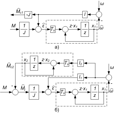 |
Figure 1 - Structure schemes of equivalent (а) and extended (б) SO with correction by rotor's angular speed |
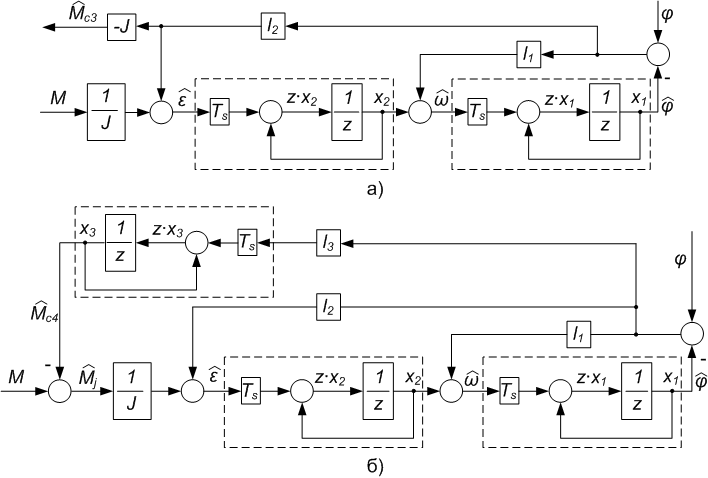 |
Figure 2 - Structure schemes of equivalent (а) and extended (б) SO with correction by rotor's angular position |
In fig. 1, 2:  - the recovered value of dynamic moment;
 - the recovered value of angular acceleration;
 - the measured value of electromagnetic moment of motor;
 - the recovered value of moment of mass;
 - the sample time of SO;
 - the recovered and measured value of rotor's angular position accordingly;
  - the recovered and measured value of rotor's angular speed accordingly;
 - the total inertia moment of electric drive;
 ,
,
 - the operator of Laplace,
 - the correctings coefficients of SO.
The design of the vector control system of PMSM and state observers was executed in the software environment Simulink of program package Matlab. The transients of the real moment of mass and recovered through SO is presented in fig. 3 (where Мn is a nominal moment of motor).
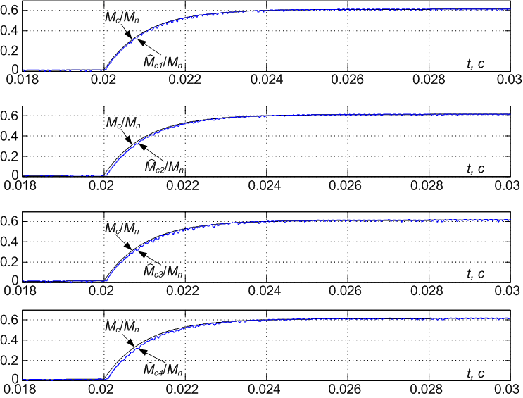 |
Figure 3 - Transients of the real moment of mass and recovered by the instrumentality of SO |
If an engine is equipped the rotor position sensor (RPS), that takes a place for electric drives based on PMSM, SO (fig. 2) can recover not only the moment of mass but also rotor's angular position (fig. 4, where ωn - nominal rotor's angular speed) [6].
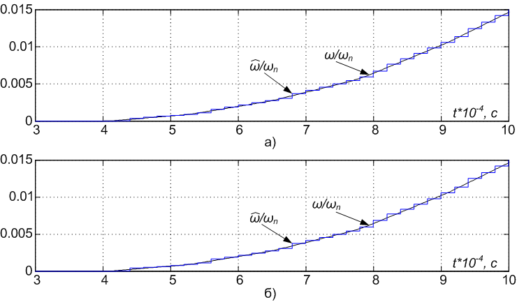 |
Figure 4 - Transients of actual angular speed and recovered through equivalent (а) and extended (б) SO with correction by rotor's angular position |
The inertia moment can’t be exactly expected usually (especially if he changes in the process of work). The inertia moment can change:
- periodically (subject to the rotation angle) in crank gear mechanisms, eccentric mechanisms, maltese-cross movement mechanisms and other;
- together with loading in traction mechanisms and lifting-and-shifting machines;
- in robotics (in a range 1:10 [4]);
- subject to a working radius in winders;
- in other mechanisms.
Therewith the SO and the speed controller are sensitive to the inertia moment deviation [4, 24] is presented in fig. 5 (JO - the calculation value of inertia moment; JР - the real value of inertia moment).
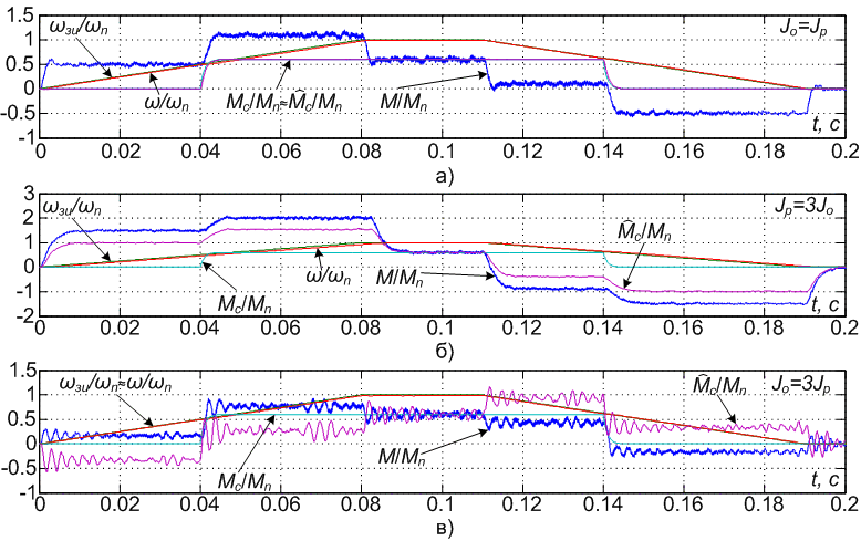 |
Figure 5 - Transients of the vector control system of PMSM during work from master of intensity |
The one of basic method for identification of inertia moment is unnormalized gradient method [22, 25]. During discretization of model of mechanical part can be used such NI methods as method of rectangles - FE, modified method of rectangles - Backward Euler (BE) and method of trapezoids - Trapezoidal (TR). The result of unnormalized gradient method for identification of inertia moment is presented in fig. 6.
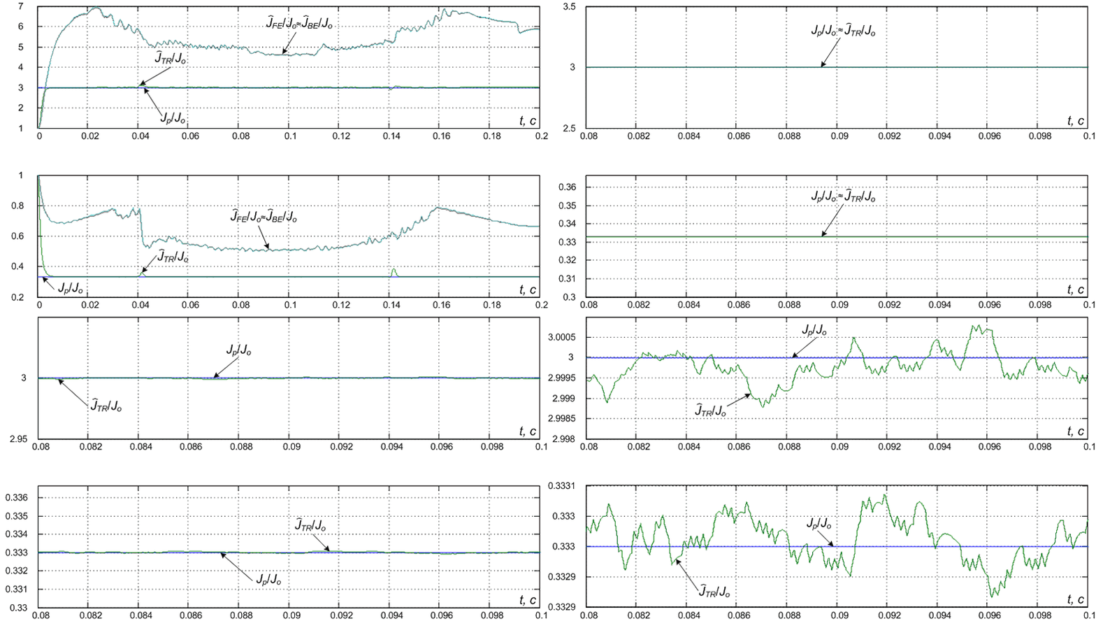 |
Figure 6 - Visualization of transients scaling of identification of inertia moment: upper fig. - when JР/JO = 3; nether fig. - when JР/JO = 1/3. (Animation is executed in the program Adobe Fireworks CS3, consists of 4th shots; the delay between shots is 1,5 sec; a delay to the repeated reproducing is 4 sec; the reproduction number is 5 cycles) |
Conclusions
- the derived SO can be used for estimate of moment of mass;
- the SO with correction by rotor's angular position can estimate an angular speed;
- the estimation of moment of mass thought the instrumentality of SO on the areas of acceleration/deceleration is erroneous in case of JР ≠ JO;
- in case of JР > JO the transients in the vector control system of PMSM become more tight;
- in case of JР < JO the transients in the vector control system of PMSM become more oscillation;
- in case of the use of Trapezoidal NI (during discretization of model of mechanical part) takes a place more exactly identification of inertia moment than at the use of methods of rectangles;
- the unnormalized gradient method of identification estimate the inertia moment in the quasisteady state with error not exceeding 0,05 %;
Future research
- research of the system of vector control system of PMSM with adaptation to the change of inertia moment and with the combined control by perturbation action;
- research of different modifications of gradient method (normalized, improved [22]) for identification of inertia moment;
- analysis of influence of noise (in a measured signals), sample time to the characteristic of SO and gradient method of identification;
- comparative analysis of gradient method with other methods of parametric identification;
- verification of the got results on the real object.
Important note
Master's work is not completed yet. Final completion: January, 2010. The complete text of work and materials on the topic can be got for an author or his adviser after the indicated date.
References
- Applications [Электронный ресурс] / Schneider Electric Motion – Motion Control, Stepper Motor, Servo Motor, Brushless DC Motor, Linear axes, Linear Motion., – http://www.schneider-electric-motion.com/index.php?scriptlet=CMS/Application&id=22&language=en&branchID=4
- Корельский Д.В. Обзор современных методов управления синхронными двигателями с постоянными магнитами / Д.В. Корельский, Е.М. Потапенко, Е.В. Васильева. // “Радіоелектроніка. Інформатика. Управління”. – 2001. – № 2. – C. 155-159.
- Казачковський М.М. Комплектні електроприводи [Навчальний посібник] / М.М. Казачковський. – Дніпропетровськ: Національний гірничий університет, 2003. – 226 с.
- Andreescu G. D. Torque-speed adaptive observer and inertia identification without current transducers for control of electric drives / Andreescu G. D., Rabinovici R. // International conference on electrical machines, Espoo, FINLANDE (28/08/2000). 2000. – pp. 1428-1432.
- Толочко О.І. Аналіз та синтез електромеханічних систем зі спостерігачами стану: [Навчальний посібник] для студентів вищих навчальних закладів / О.І. Толочко. – Донецьк: Норд-Прес, 2004. – 298 с.
- Толочко О.И. Особенности идентификации электромеханической постоянной времени и момента статического сопротивления в системах позиционного электропривода / О.И. Толочко, П.И. Розкаряка, Г.С. Чекавский. // Тематический выпуск «Проблемы автоматизированного электропривода. Теория и практика» научно-технического журнала «ЭЛЕКТРОИНФОРМ» – Львов: ЕКОинформ, 2009. – С. 74-75.
- Идентификация электромеханической постоянной времени в системах с наблюдателями состояния, восстанавливающими статический момент / О.И. Толочко, П.Х. Коцегуб, П.И. Розкаряка, Г.С. Чекавский. // Тематический выпуск «Проблемы автоматизированного электропривода. Теория и практика» научно-технического журнала «ЭЛЕКТРОИНФОРМ» – Львов: ЕКОинформ, 2009. – С. 59-62.
- Титков С.Ю. Исследование динамики управления приводом шарнира манипулятора сборочного робота с использованием современных методов аналитического конструирования оптимальных регуляторов [Электронный ресурс] / Портал магистров ДонНТУ, – http://www.masters.donntu.ru/2007/kita/titkov/diss/index.htm
- Соколов Н.А. Исследование и разработка наблюдателя состояния с адаптацией к изменению параметров объекта управления [Электронный ресурс] / Портал магистров ДонНТУ, – http://www.masters.donntu.ru/2009/eltf/sokolov/diss/index.htm
- Дворак В.М. Цифровий електропривод: [Навчальний посібник] для студентів напрямку 6.050702 «Електромеханіка» спеціальності «Електричні системи і комплекси транспортних засобів» денної та заочної форм навчання / В.М. Дворак. – Керч: Керченський державний морський технологічний університет, 2010. – 220 с.
- Потапенко Е.М. Основы теории автоматического управления / Е.М. Потапенко, А.Е. Казурова. – Запорожье: ЗНТУ, 2007. – 162 с.
- Высокоточное управление скоростью двухмассовой неопределенной электромеханической системой / Е.М. Потапенко, А.Е. Казурова, Е.В. Душинова, Н.В. Ивочка. // Радіоелектроніка, інформатика, управління Науковий журнал 2009 — № 1(20) – Запоріжжя: ЗНТУ, 2009. – С. 147-154.
- Акимов Л.В. Системы управления электроприводами постоянного тока с наблюдателями состояния [Монография] / Л.В. Акимов, В.Т. Долбня, В.И. Колотило. – Харьков: ХГПУ, 1998. – 117 с.
- Моделювння електромеханічних систем: [Підручник] / О.П. Чорний, А.В. Луговой, Д.Й. Родькін та ін. – Кременчук, 2001. – 410 с.
- Kalman R. Contributions to the theory of optimal control / Kalman R. // Bol. Soc. Mat. Mexicana, 1960. – №35. – P. 102-119.
- Кузовков Н.Т. Модальное управление и наблюдающие устройства / Н.Т. Кузовков. – М.: Машиностроение, 1976. – 184 с.
- Изерман Р. Цифровые системы управления / Изерман Р. – М.: Мир, 1984. – 541 с.
- Luenberger D.C. An Introductions to Observers / Luenberger D.C. // Proc. IEEE Transformation on Automatic Control. – 1971. – December. – P. 596-602.
- Beineke S. Online identification of nonlinear mechanics using extended Kalman filters with basis function networks / Beineke S., Schutte F., Grotstollen H. // Proceedings: Conference on Industrial Electronics, Control and Instrumentation, 1997. – pp. 316-321.
- Башарин А.В. Управление электроприводами: [Учебное пособие] для вузов / А.В. Башарин, В.А. Новиков, Г.Г. Соколовский. – Л.: Энергоиздат. Ленингр. отд-ние, 1982. – 392 с.
- Виноградов А.Б. Векторное управление электроприводами переменного тока / А.Б. Виноградов. – ГОУВПО «Ивановский государственный энергетический университет имени В.И. Ленина». Иваново, 2008. – 298 с.
- Ljung L. System Identification – Theory For the User, 2nd ed / Lennart Ljung. – PTR Prentice Hall, Upper Saddle River, N.J., 1999. – 609 pp.
- Соколовский Г.Г. Электроприводы переменного тока с частотным регулированием: [Учебник] для студ. высш. учебн. заведений / Г.Г. Соколовский. – 2-е изд., стер. – М.: Издательский центр «Академия», 2006. – 272 с.
- Божко В.В. Дослідження спостерігачів невизначеностей у системах електроприводу на базі СДПМ / В.В. Божко, В.М. Трандафілов // Донбас-2020: перспективи розвитку очима молодих вчених: Матеріали V науково-практичної конференції. м. Донецьк, 25-27 травня 2010 р. – Донецьк, ДонНТУ Міністерства освіти і науки, 2010. – C. 229-233.
- Трандафілов В.М. Особливості градієнтного метода ідентифікації моменту інерції електроприводу / В.М. Трандафілов, О.І. Толочко, В.В. Божко // Автоматизація технологічних об’єктів та процесів. Пошук молодих. Збірник наукових праць X Міжнародної науково-технічної конференції аспірантів та студентів в м. Донецьку 18-20 травня 2010 р. – Донецьк, 2010. – С. 260-262.
Materials on the theme of master's work: About author |

