

| Main page of DonNTU | Search system of DonNTU | Page of DonNTU master's degree students | |
 |
UKRAINIAN |  |
RUSSIAN |
 |
Bugayov RuslanFaculty: Engineering Mechanics and EngineeringSpeciality: Metal-cutting machine-tools and systems |
| Biography |
1 Introduction
2 Actuality of work
3 Purpose and tasks of work
4 Review of existing designs devices for MAM
5 The design part
6 The theoretical part
7 The practical part
8 Final Part
Literature
Magnetic-abrasive machining (MAM) - abrasive treatment which is performed by moving the workpiece and the abrasive grains relative to each other in a magnetic field. Summary of magnetic-abrasive processing is that the ferromagnetic abrasive powder mass, compacted energy of the magnetic field carries abrasive effect on the treated detail. Magnetic-abrasive method can successfully to handle the surface: cylindrical interior and exterior, flat bodies of revolution with a curved generatrix screw etc. The most common uses of magnetic-abrasive treatment is to reduce the roughness on the machined surfaces with a simultaneous increase of the quality characteristics of the surface layer [1].
To perform the master's works, I have analyzed the known design of devices for magnetic-abrasive machining (MAM) terminal instrument in a magnetic field. As a consequence, I found that the devices for MAM are either narrow technological capabilities, or the complexity of design in connection with a large number of kinematic chains.
Based on the above said, in my work, I would like to develop a device for magnetic-abrasive machining of polyhedral through-away hard-alloy plates on the basis of horizontal milling machine.
Improved accuracy and quality of surfaces of machine parts and tools is the one of the priorities of mechanical engineering. To achieve these goals is currently widely used is the method of MAM, which is one of the promising new treatment methods, and allows for a variety of physical and mechanical properties of materials (steel, hard alloy, nonferrous metals and alloys, glass and other non-metals) to obtain low settings roughness. The role of the cutting tool with MAM performs magneto-abrasive powder which has both high magnetic and cutting qualities.
The method of MAM provides roughness parameters Ra 0,01-1 mm, reduction and waviness grannosti. This increases the contact strength and wear resistance of parts, increases the length of the reference profile. The method has the ability to handle both soft and viscous, and non-metallic materials. The study of this method in a large number of works performed in the former USSR and abroad. Investigations were focused on the development of new methods and devices for their implementation, the study of technological capabilities of the process, and the phenomena accompanying the process [5, 6].
That’s any the topic of master's work is relevant as MAM is a modern processing techniques that provide high quality surface finish.
The purpose of this study is to develop a design of the device for magnetic-abrasive machining of polyhedral through-away hard-alloy plates in the bath magnet implemented on a horizontal milling machine.
The main objective of this work is to update the horizontal milling machine for magnetic-abrasive processing in magnetic ring system.
Known installation for MAM-cutting tool [2]. Processing of parts made at the expense of creating conditions under which a relatively uniform flow of the processed surfaces of magnetic abrasive powder in magnetic field, achieved through job specific trajectory of parts and their arrangement in a magnetic field that takes into account data on the magneto-rheological characteristics of the magnetic-abrasive powder materials.
The work piece is rotated around its own axis, move around the axis of circular bath formed by pole pieces of limited height and reversible move along the circular bath.
It is known that MAM details in an annular magnetic gap, the part moves in an environment of magnetic-abrasive powder retained by the magnetic field formed in front of a hardened zone with a share ferroabrasive powder, which is a fan-shaped formation. The formation of such a compacted zone, its size and behavior in the MAM primarily due to:
-magneto-rheological properties of magnetic-abrasive powders, namely, the geometric dimensions and shape of particles, the coefficients of friction pairs in powder-powder and detergent - workpiece friction angle of magnetic-abrasive tool (MAT), magnetic properties;
-geometry of the working zones of magnetic gaps;
Displacement characteristics of processed workpieces in the process of MAM
For efficient processing of the entire working surface of parts, including the surface of the grooves must be the optimal ratio between the two unconnected parameters MAM:
-pressure magnetic-abrasive powder, formed by the magnetic field in the MAT on the work surface;
-MAT-speed particles on the machined surfaces.
Simply increasing the strength of the magnetic field in the working zones of magnetic gaps, providing clamping MAT particles to the treated surface and the formation of the most "solid" MAT reduces the ability of the body surface of work piece and unacceptable under MAM grooves. Increase of speed parts, leads to an increase in dynamic pressure of the particles on the surface areas of MAT, but it also leads to the appearance of compacted zones.
Implementation of the first path is acceptable for treatment of external surfaces of parts of simple shape - the bodies of revolution, planes, when you can use a small magnetic gap width. When processing of parts of complex spatial configuration is often necessary to use a large magnetic gap width, the achievements in which high magnetic induction associated with a number of technical difficulties and high energy costs. In addition, during the processing of parts with longitudinal or helical grooves are filled to the volume of powder, which, clinging to the surface grooves, creating shadows, remaining in the processing of almost stationary.
Implementation of the second track - "dynamic" limited pressing of magnetic rheological characteristics of MAT when the relative movement of particles on the surface of the MAT should observe the conditions under which it will be stable interaction portions of powder are in the grooves, with the bulk of MAT, which leads to its movement on the machined surfaces due to magnetic-rheological forces. That is necessary to achieve compliance with the terms of the critical driving stress in the mass formed by the MAT. Achievement of the requirements for the implementation of this path is closely linked to the second condition necessary to achieve efficient processing of magnetic-abrasive method.
Receipt of the required relative velocity of the particles on the MAT piece surface, especially on surface grooves may be the case when the angle of inclination of the surface grooves on the direction of the main motion processing (rotation around the axis of the circular bath) will be responsible for the angle of friction MAT. To realize this can be due to the slope of parts, and thus machined surfaces on the direction of the main motion. There is no need to use large values of magnetic induction in the working zones of magnetic gaps.
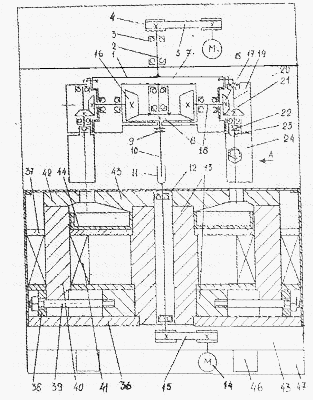
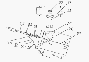
Figure 1 shows a device that implements the method of magnetic-abrasive processing. It consists of a head mounted on the spindle bearings 2 at 3. At one end of the spindle mounted pulley 4, a belt connecting the spindle 5 2 engine 6. Instead of a belt transmission can be used by any reducer or animated gear. At the other end of the spindle 2 on the bearings 7 established by the Central bevel gears 8, 9 through the sleeve the shaft 10. Shaft 10 via a movable splined or keyway connecting with a telescopic shaft 11, which is installed in a central magnetic conductor 13 of the magnetic system. Shaft 11 is connected to motor 14 belt drive 15. Alternatively, the drive of the central conical wheel 8 can be carried out through the shaft 10, located in the hollow spindle 2. At the head of 1 set bevel gear, meshed with the bevel gears 8. It consists of gears 16 and 17 and shaft 18. Coaxially with the shaft bore 18 in head 1 head set 19. It is set in bearings shaft 20 with bevel wheel 21 meshed with a wheel 17. On the lower end of the shaft 20 with a sleeve 22 connected to shaft 23 angle head 24 (Fig. 2) with the bevel wheel 25 at the other end. Wheel 25 is in engagement with the wheel 26 is planted on the spindle 27. The output end of the spindle through a sleeve Hook 28 is connected to the clamping mechanism to clamp the work piece 29. In this case, used collets clamping mechanism 30. The main body of the angle head mounted oscillating drive 31, that with the lever 32, pivot 33, connecting rod 34 and bearing 35 is connected to the clamping mechanism 30.
Magnetic system of the device consists of a central magnetic core 13, rigidly mounted in the lower 36 and upper 37 plates with diamagnetic material. To the central magnetic core with staples 38 and pins 39 are pressed side cores 40. They wore the coil 41. On the side of the magnetic circuit 40, the top of the fixed outer pole pieces 42. At the top of the central magnetic core 13 is installed central pole piece 43, made in the form of a disk, the radial outer surface and converted to its side surfaces of the outer pole pieces 42 formed between an equidistant gap, forming a circular bath. On the upper plate 37 is supported pallet 44. The magnetic system is installed on the table 45. Table 45 is installed on the vertical guide 46 on the frame 47.
Method of magnetic-abrasive processing of the final volume of cutting tools is as follows:
Magnetic gap machine, the ring-shaped bathtub, filled with magneto-abrasive powder retained in the working area of the magnetic field produced by direct current, submitted to the coils 41 of electromagnets. Useable tool 29 clamped in the collet clamping mechanism 30. The heads 19 rotate around its axis, opposite to the main motion (rotation around the axis of the ring baths). The device with parts located in such a situation in which the parts can be found at the entrance to the working area of the magnetic gap. The induction in the magnetic gap raised to a value equal to the optimum value for MAO-material tool in a circular magnetic system with the corresponding value of the magnetic gap. Included is the engine drive head 1 and the engine 14 provides the central bevel gears 8. Table 45, together with the magnetic system with vertical movement of the drive smoothly rises to a partial or total immersion work piece tool 29 in a vertical magnetic system bath filled with magneto-abrasive powder (Fig.3).
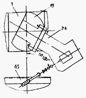
Gear 6 driven around on wheels 8, receives an additional rotation of the engine 14 through drive 15, shaft 11 and the sleeve 9. A pair of gears 17 and 21, 25 and 26 of the total rotation is transmitted to the spindle 27. In addition, the tool 29 reported vibrational motion actuator 31, aimed at radius circular bath. The direction and speed of the tool 29 about its axis, and the frequency and amplitude of vibrational motion along the radius of circular bath depends on the type of instrument, its construction, machined surfaces, the material of which it is made, the type of magnetic-abrasive powder.
The disadvantages of this setup are: narrow technological opportunities associated with the impossibility of angle of attack within the 5-30 ° in the processing of hard plates, as well as design complexity due to the presence of an additional device, which passes through the magnetic system.
Known universal head for MAM [3], the essence of which is explained concept and mechanism of the PTO.
Universal head (Fig. 4) consists of five modules: Drive 1, handout 2, angular 3, 4, and an intermediate spindle 5. The drive unit 1 is attached to the machine spindle, such as milling, the tool-cone on the mandrel 6, or the spindle can be made appropriate mounting surface for installation of units and details the head.
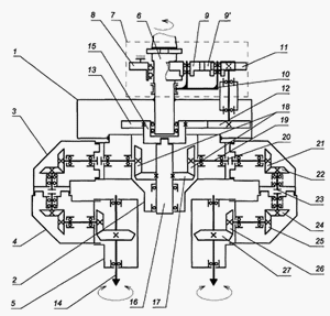
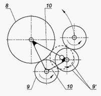
PTO (Fig. 5) consists of a motionless located spindle machine and a central cylindrical wheel 8 mounted on the mandrel 6 on bearings and the idler gears 9 and 9 'mounted on the rotating mandrel 6 on plate 10 and connected on one side with central cylindrical wheel 8, and on the other side with a guitar replacement wheels 11, 12 and 13.
Static connection with the drive unit 1 (Fig. 4), distributing module 2 contains a uniformly arranged in a circle, connected in corner modules 3, 4 and TX spindle 5, which can rotate relative to each other and relatively dispensing module, and are designed to provide procurement correct spatial position.
The kinematic chain connecting the guitar replacement wheels 11, 12, 13 with working spindles 14 spindle module 5, consists of a cup 15, located at the bottom of the mandrel 6, the shaft 16 dispensing module 2, for example, mechanical slot or radial blade, the shaft 16 with fixed it a central bevel wheel 17, connected to the bevel wheel-SAT 18, which is enshrined in the radial shaft 19, clutch 20, the conical transmission 21-22, sleeve 23, bevel gears 24-25, 26 -27. At the working spindles fixed clamping device with blanks (on the scheme are not shown). Structurally, the node for the transfer of torque from gear 13 to shaft 16 with a conical wheel 17 can be executed as the shaft with the bearings installed in boring in the lower end of the mandrel 6 and the coupling (or end slot). Gears 11, 12 and 13 make up a guitar replacement wheels. In the first place to change the gear ratio of the kinematic chain from the main wheel 8 to 14 are working spindle gear wheel 11, as the most affordable, and secondarily pair of wheels 12 and 13. Additional parasitic wheel 9 'reversible in the position shown dotted in Figure 5. At the same time it catches a central cylindrical wheel 8 and the wheel 11, and the main parasitic wheel 9 is removed from the head.
Universal head for MAM works as follows. In the initial position (Universal head raised above the bathtub ring magnet system) is the installation of blanks in the clamping devices and bring them to the correct spatial position by turning the corner, 3 of the 4 and 5 modules spindle relative to each other and on distributing a module 2. When lowering down the machine spindle hub carrier, cut a ring immersed in a bath of magnetic system, pre-filled with magneto-abrasive powder.
After immersing the work pieces to the desired depth, which is determined by the height of the magnetic pole pieces of the system (not shown), the universal head of the rotational motion is granted and, thus, billet rotating in a bath ring around its axis (the main working-class movement).
During the rotation of the universal head and as a result, the drive module 1, the parasitic wheels 9 and 9 'revolve around the stationary wheel 8, thus receiving a rotational motion, and transmit it to the wheel 11 guitar replacement wheels. After the wheels 11, 12 guitars replacement wheels, a glass 15 and shaft 16 is driven by a central bevel gears 17. Coming from the central conical wheel 17 movement is transmitted to the bevel wheel 18 and then through the clutch 20, bevel gears 21-22, sleeve 23, conical transmission 24-25, 26-27 in the working spindles 14 which are fixed clamping device with blanks (on the scheme not shown). There is a blank with a rotational movement around its axis (a subsidiary motion) required for the uniform treatment of finite and axial instruments. At the same time by selecting wheels guitar replacement wheels can be made strict alignment of the rotational motions of most of the head and working spindle 14, ie the main motion and the motion of division.
After processing the rotational motion stops and the universal head up to the starting position.
For processing tools with left-sided spiral grooves for the chip to change the direction of rotation of the working spindle at a constant direction of rotation of the head, the main parasitic wheel 9 is removed from the head, while the additional parasitic wheel 9 'is introduced into mesh with the central cylindrical wheel 8 and the wheel 11 guitar replacement wheels.
The disadvantage is the complexity of design build guitars replacement wheels and low reliability due to the large number of kinematic chains.
Known head for MAM hard-alloy plates [4], which consists of the drive module with the PTO, which consists of a fixed central cylinder wheel mounted on the mandrel bearings and parasitic gear mounted on rotating bars on the plate and connected to one side with a central cylindrical wheel and the other with a guitar replacement wheels drive module and a central conical wheel installed in the drive module dispensing module mounted on the lower end of the drive module, and which has radially arranged on the shaft bearings on the input end of which a bevel-wheel, which meshes with the central bevel wheel drive module spindle units, which are uniformly arranged in a circle on the periphery of the dispensing module. Spindle units consist of a series of interconnected, with the possibility of angular movement relative to one another angle, intermediate and spindle units with working-spindle, with the output shaft end of each dispensing module is connected to a working spindle of a kinematic chain of transfers and intermodule connection middleware and spindle modules are interchangeable .
The disadvantage of this head design is the complexity of establishing guitar replacement wheels, and low reliability due to the large number of kinematic chains.
This part of the work accomplished by the following tasks:
1. Modernization a horizontal milling machine for magnetic-abrasive machining hard-alloy plates.
2. Develop the working drawings collection modernization.
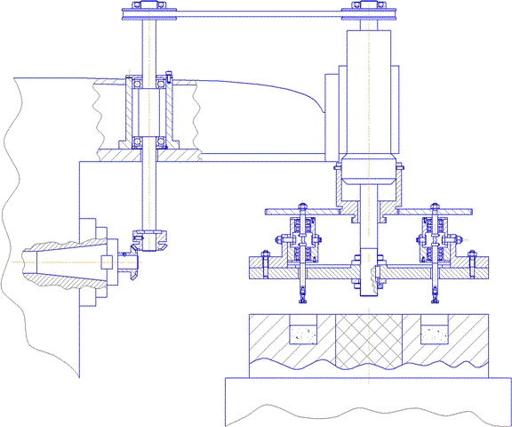
The problem is solved by the fact that the design head for MAM, which contains the spindle and drive-ins, drive module is fixed onto the spindle. On the surface of the drive module fixed spindle modules in which the spindle is located at one end of which featured multi-faceted processed wafers, and the second - the wheel, which is its working surface in contact with the working surface of the glass, still mounted on the end of the quills spindle host machine. Head for MAO consists of a drive module, which is a disc rigidly mounted on the spindle. On the front surface of the disk drive uniformly on a circle are situated spindle heads, which are located at one end of the spindle which are located in progress, multifaceted plates, the second - the gear wheel. Wheel your work surface con-clocks with a working surface glass, which is secured in position. Glass has echelon work surfaces that may contact the respective gear wheel diameter. The formation of angle of attack of the spindle is able to rotate at the desired angle through the implementation of the spindle with two parts connected by a flexible shaft (Fig. 6).
part of the work is realized by solving the following problems:
1. Determine the shape of a model magnetic-abrasive powder (MAP).
2. Determine the geometric dimensions of the model.
3. Calculation of the GRACE influence of magnetic field on the distance between the models powder.
The practical part of the master's work involves carrying out the experiment. I and my scientific adviser are planning the following sequence of the experiment:
1. Perform a weighted MAP on an analytical balance.
2. Compute the geometric model of the MAP
3. Perform a measurement of the distance between the grains of MAP on the microscope outside of the magnetic field.
4. Perform a measurement of the distance between the grains of MAP on the microscope in a magnetic field.
5. Compare the results of measurements and draw conclusions.
Device for MAO works as follows: turn on the drive of the main motion machine, and the movement is transmitted through the bevel gear and belt predate on the spindle, which enshrined the disk begins to rotate and through the contact of working surfaces of glass with a toothed wheel starts to spin with a spindle attached to said They processed plates. Machine table moves up before the processed wafers are not plunge into a circular magnetic system, filled with abrasive powders. After processing the table moves down, turns off the drive machine and processed to replace the plate processed.
![Fig. 7 - The magnetic-abrasive processing of polyhedral through-away hard-alloy plates [10, 11] The magnetic-abrasive processing of polyhedral through-away hard-alloy plates [10, 11]](bugayov_animation.gif)
In carrying out the work of master design of the device for magnetic-abrasive machining of polyhedral through-away hard-alloy plates in a magnetic ring system is implemented on a horizontal milling machine.
In the future we plan to produce a series of experimentation with magnetic-abrasive powder. As a result of an experiment to determine the shape of the model, to calculate and analyze a mathematical model of the magnetic-abrasive powder.
During the process of writing, the master’s work hasn’t completed yet. Final completion: December, 2010. The full text of work and materials on the theme could be received from the author or him scientific adviser after the indicated date.
| Biography |
| Main page of DonNTU | Search system of DonNTU | Page of DonNTU master's degree students | |