|
|
Source of information: http://web.iitd.ac.in/~suniljha/nanofinishing.pdf
Magnetic abrasives are emerging as important finishing methods for metals and
ceramics. Magnetic Abrasive Finishing is one such unconventional finishing process
developed recently to produce efficiently and economically good quality finish on the
internal and external surfaces of tubes as well as flat surfaces made of magnetic or
non-magnetic materials. In this process, usually ferromagnetic particles are sintered
with fine abrasive particles (Al2O3, SiC, CBN or diamond) and such particles are called ferromagnetic abrasive particles (or magnetic abrasive particles). However,
homogeneously mixed loose ferromagnetic and abrasive particles are also used in
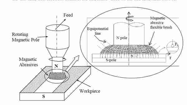
certain applications. Fig. 1 shows a Plane MAF process in which finishing action is
generated by the application of magnetic field across the gap between workpiece
surface and rotating electromagnet pole. The enlarged view of finishing zone in Fig.
4 shows the forces acting on the work surface to remove material in the form of chips.
Force due to magnetic field is responsible for normal force causing abrasive
penetration inside the workpiece while rotation of the magnetic abrasive brush (i.e.
North pole) results in material removal in the form of chips.
The magnetic abrasive grains are combined to each other magnetically between
magnetic poles along a line of magnetic force, forming a flexible magnetic abrasive
brush. MAF uses this magnetic abrasive brush for surface and edge finishing. The
magnetic field retains the powder in the gap, and acts as a binder causing the powder
to be pressed against the surface to be finished [1]. 3D minute and intricately curved
shape can also be finished along its uneven surface. Controlling the exciting current of
the magnetic coil precisely controls the machining force of the magnetic abrasives on
the work piece [2].

Since the magnitude of machining force caused by the magnetic field is very low
but controllable, a mirror like surface finish (Ra value in the range of nano-meter) is
obtained. In MAF, mirror finishing is realized and burrs are removed without
lowering the accuracy of the shape. These fine finishing technologies using magnetic
abrasives have a wide range of applications. The surface finishing, deburring and
precision rounding off the workpiece can be done simultaneously. MAF can be used
to perform operations as polishing and removal of thin oxide films from high speed
rotating shafts. Shinmura [3] have applied MAF to the internal surface of work
pieces such as vacuum tubes and sanitary tubes.
Fig. 2 shows the magnetic abrasive jet finishing of internal surface of a hollow
cylindrical workpiece. It's a variant of MAF process in which working fluid mixed
with magnetic abrasives is jetted into the internal surface of the tube, with magnetic
poles being provided on the external surface of the tube [4]. The magnetic abrasives
in the jet mixed with fluid are moved to the internal surface by magnetic force, where
the magnetic abrasives finish the internal surface effectively and precisely.
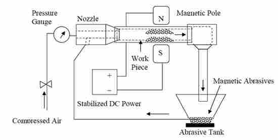
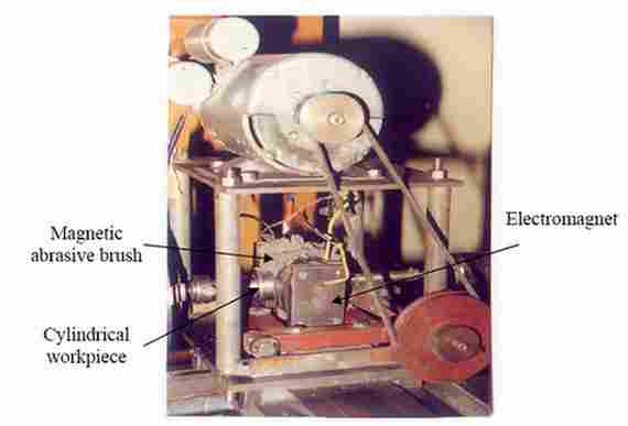
Fig. 3 shows a schematic of a typical MAF process in which the workpiece to
be machined is located between two magnetic poles. The gap between the
workpiece and the pole is filled with a magnetic abrasive powder. The magnetic
abrasive grains are linked to each other magnetically between the north and south
magnetic poles along the lines of magnetic force, forming a flexible 2-5 mm long
magnetic brush. MAF uses this magnetic abrasive brush for surface and edge
finishing. The magnetic field retains the powder in gaps, and acts as a binder
causing the powder to be pressed against the surface to be finished [5]. A rotary
motion is provided to cylindrical workpiece, such as ceramic bearing rollers
between magnetic poles. Also axial vibratory motion is introduced in the magnetic
field by the oscillating motion of magnetic poles to accomplish surface and edge
finishing at faster rate and better quality.
The process is highly efficient and the removal rate and finishing rate
depends on the workpiece circumferential speed, magnetic flux density, working
clearance, workpiece materials, and size, type and volume fraction of abrasives.
The exciting current of the magnetic coil precisely controls the machining force
transferred through magnetic abrasives on the work piece.
Since the magnitude of machining force caused by the magnetic field is very low, a mirror like surface finish (Ra value in the range of nano-meter) can be obtained. Results were reported in the literature of finishing stainless steel rollers using MAF to obtain final Ra of 7.6 nm from an initial Ra of 0.22 µm in 30 seconds [6].
Traditional methods of finishing high precision lenses, ceramics and
semiconductor wafers are very expensive and labor intensive. The primary
obstacle in manufacturing high precision lenses is that lenses are usually made of
brittle materials such as glass, which tends to crack while it is machined. Even a
single microscopic crack can drastically hinder a lens's performance, making it
completely ineffective for its intended application. Every device that uses either
lasers or fiber optics requires at least one high precision lens, increasing its
demand higher than ever.
Lens manufacturing can be classified into two main processes: grinding and
finishing. Grinding gets the lens close to the desired size, while finishing removes
the cracks and tiny surface imperfections that the grinding process either
overlooked or created. The lens manufacturer generally uses its in-house opticians
for the finishing process, which makes it an arduous, labor-intensive process.
Perhaps the biggest disadvantage to manual grinding and finishing is that it is nondeterministic.
To overcome these difficulties, Center for Optics Manufacturing
(COM) in Rochester, N.Y. has developed a technology to automate the lens
finishing process known as Magnetorheological Finishing (MRF) [7].
The MRF process relies on a unique "smart fluid", known as
Magnetorheological (MR) fluid. MR-Fluids are suspensions of micron sized
magnetizable particles such as carbonyl iron, dispersed in a non-magnetic carrier
medium like silicone oil, mineral oil or water. In the absence of a magnetic field,
an ideal MR-fluid exhibits Newtonian behaviour. On the application of an external
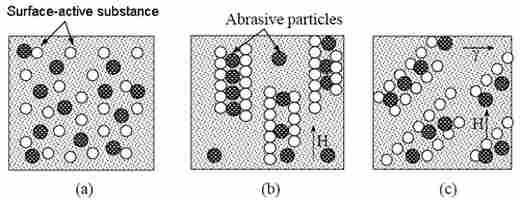
magnetic field to a MR-suspension, a phenomenon known as Magnetorheological
effect, shown in Fig.4, is observed. Fig. 4a shows the random distribution of the
particles in the absence of external magnetic field; In Fig. 4b, particles magnetize
and form columns when external magnetic field is applied. The particles acquire
dipole moments proportional to magnetic field strength and when the dipolar
interaction between particles exceeds their thermal energy, the particles aggregate
into chains of dipoles aligned in the field direction. Because energy is required to
deform and rupture the chains, this micro-structural transition is responsible for
the onset of a large "controllable" finite yield stress [8]. Fig. 4c shows an
increasing resistance to an applied shear strain, γ due to this yield stress. When the
field is removed, the particles return to their random state and the fluid again
exhibits its original Newtonian behaviour.
Rheologically, the behaviour of MR-fluid in presence of magnetic field is described by Bingham Plastic model [9]:

where τ is the fluid shear stress, τ0 is magnetic field induced yield shear stress, η is dynamic viscosity of MR-fluid and γ’ is Shear rate [s-1].
The dynamic viscosity is mostly determined by the base fluid. The field
induced shear stress τ0 depends on the magnetic field strength, H. The strength of
the fluid (i.e. the value of static yield shear stress) increases as the applied
magnetic field increases. However, this increase is non-linear since the particles
are ferromagnetic and magnetizations in different parts of the particles occur nonuniformly
[10]. MR-fluids exhibit dynamic field strength of 50-100 kPa for
applied magnetic fields of 150-250 kA/m (~2-3 kOe) [11]. The ultimate strength
of MR-fluid is limited by magnetic saturation.
The ability of electrically manipulating the rheological properties of MR-fluid
attracts attention from wide range of industries and numerous applications are
explored [12]. These applications are use of MR-fluid in shock absorbers and
damping devices, clutch, brakes, actuators, and artificial joints. The magnetic field
applied to the fluid creates a temporary finishing surface, which can be controlled
in real time by varying the field's strength and direction. The standard MR fluid
composition is effective for finishing optical glasses, glass ceramics, plastics and
some non-magnetic metals [13].
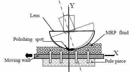
In the Magnetorheological finishing process as shown in Fig. 5, a convex, flat,
or concave workpiece is positioned above a reference surface. A MR fluid ribbon
is deposited on the rotating wheel rim, Fig. 6. By applying magnetic field in the gap, the stiffened region forms a transient work zone or finishing spot. Surface
smoothing, removal of sub-surface damage, and figure correction are
accomplished by rotating the lens on a spindle at a constant speed while sweeping
the lens about its radius of curvature through the stiffened finishing zone [14].
Material removal takes place through the shear stress created as the
magnetorheological polishing ribbon is dragged into the converging gap between
the part and carrier surface. The zone of contact is restricted to a spot, which
conforms perfectly to the local topography of the part. Deterministic finishing of
flats, spheres, and aspheres can be accomplished by mounting the part on rotating
spindle and sweeping it through the spot under computer control, such that dwell
time determines the amount of material removal.
![A Vertical MRF Machine [14] A Vertical MRF Machine](stan11.jpg)
The MR-polishing fluid lap has following merits over traditional lap:
1. Its compliance is adjustable through the magnetic field.
2. It carries heat and debris away from the polishing zone.
3. It does not load up as in grinding wheel.
4. It is flexible and adapts the shape of the part of the workpiece which is in its
contact.
The computer controlled Magnetorheological finishing process has demonstrated the
ability to produce the surface accuracy of order 10-100 nm peak to valley by
overcoming many fundamental limitations inherent to traditional finishing techniques
[7].These unique characteristics made Magnetorheological Finishing as the most
efficient and able process for high precision finishing of optics. MRF makes finishing
of free form shapes possible for first time.
Applications that use high precision lenses include medical equipment such as
endoscopes, collision-avoidance devices for the transportation industry, scientific
testing devices and military's night vision equipment like infrared binoculars. Missiles
are equipped with a wide variety of high precision lenses for navigation, target
location, and other functions. The nano diamond doped MR fluid removes edge chips,
cracks, and scratches in sapphire bend bars.
References
|
|