| Язык | Мова |
 |
 |
| Язык | Мова |
|
|

Faculty: |
Mechanical Engineering |
Speciality: |
Computer designing of mechatronic mining equipment |
Theme of thesis: |
A mathematical model of the process of powered support DM |
Supervisor: |
Semenchenko Anatoliy |
Relevance of the problem. The basis of modern mining systems for are powered roof supports, the design and parameters of which should provide reliable high-performance work of the entire complex of equipment and safety of staff. Powered support, as one of the basic machinery of mining systems, largely determines its performance. In this context, rationale and development of research methods and calculating the parameters in the design of powered supports with features that ensure their effective operation in conditions of increasing load on the breakage face is an actual scientific and practical problems, the existing branch value.
Analysis of research and scientific novelty. Performance analysis and dimensioning of powered roof supports are devoted to the work of several authors. The analytical methods, experimental studies. However, at the present stage the results obtained allow to solve local problems and do not provide a solution to the optimization problem based on the complete mathematical model of powered support. In this paper, a mathematical model of the kinematic parameters of powered support, the mathematical model of the roof supports and hydraulic drive systems based on functionally complete components that addresses the challenge of research, calculation and optimization of the powered supports.
The purpose and objectives of the work. The aim is to develop a modern research parameters sections powered supports for their modernization, providing more efficient operation of mechanized complexes.
To determine the kinematic parameters used by a mathematical model:
![]()
Where
YK – output vector whose components are the coordinates of points 3, 4, 5,7, 8, 9, 10;
lC and lG – length of hydraulic jack and stabilizing jacks, respectively. Are the arguments of the vector function fK;
P – vector of structural parameters of the four.
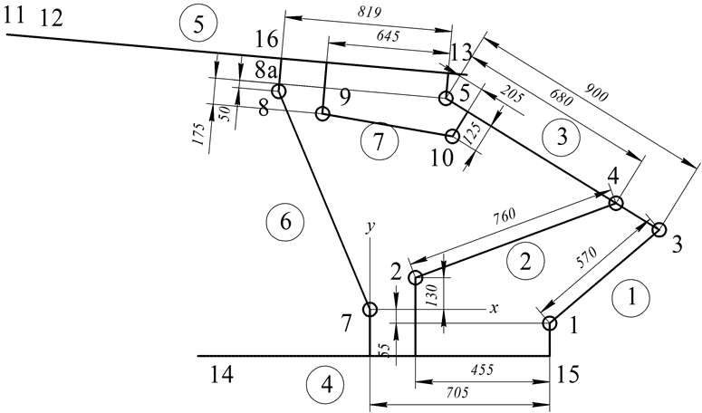
Figure 1 - The design scheme for the determination of kinematic parameters. |
The initial data are the design parameters of the powered support:
Distances between points are the restrictions on the basis of which the equations of kinematics.
![]() , m;
, m;
![]() , m;
, m;
![]() , m;
, m;
![]() , m;
, m;
![]() , m;
, m;
![]() , m;
, m;
l54 = 0,68 m; l24 = 0,76 m; l13 = 0,57 m;
lC and lG are variables.
Coordinates of fixed points of 7, 2, 1:
x7= 0; x2= 0,25; x1= 0,705;
y7 = 0; y2= 0,13; y1= -0,055.
Решение.
Based on the restrictions a system of equations:
System of equations 14-th order is solved with a software Mathcad.
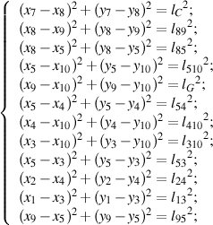
On the basis of kinematics models we construct a graph of the x coordinate of point 1 n the length of hydraulic jack d = f(t), or three positions of the stabilizing hydraulic jack lG = 0,5; 0,7; 0,8 m.
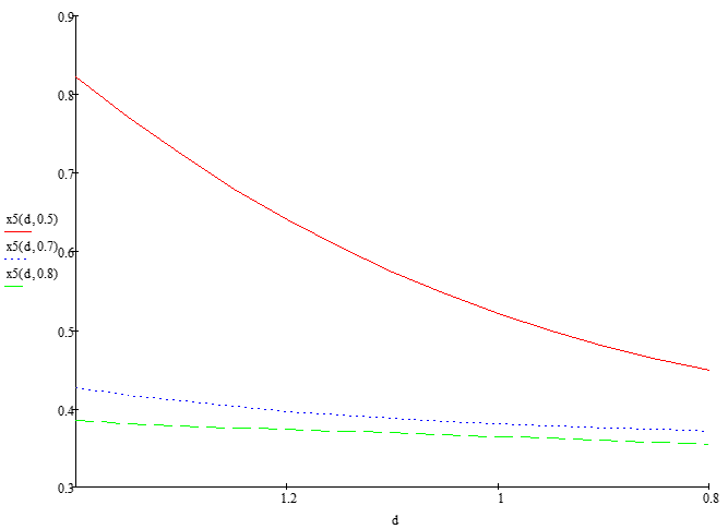
Figure 2 - The graph of x5 = f(d,lG). |
Figure 3 - Trajectory of points 3,4,5,8,8а,9,10. |
Animation of the process of powered support. |
The graph shows that in the process of closing the base is shifted to the rock face, which has a positive impact on the roof.
At this stage of the implementation is developed simplified model of powered support based on the following functionally complete components:
From the FCC compile simplified scheme of powered support and pumping station. Spatial moved mass replace linearly moving mass.
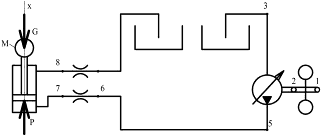
Figure 4 - The design scheme. |
Description of the design scheme:
Asynchronous motor rotates the pump through the shaft 2. The pump takes hydraulic fluid from Hydraulic tank and pumps it into the pipe is 5-6. From the pipeline, through the throttle 6-7, the fluid enters the piston cavity of the hydraulic jacks. Throttle 6-7 simulates the resistance control valve. The pressure of working fluid on the piston creates a force P, which, overcoming the force G, displaces fluid from the rod end 8. Working fluid returns to the hydraulic tank through a throttle.
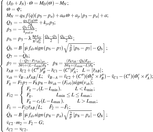
Based on a design scheme making up the system of equations:
where
JD – the moment of inertia of the motor rotor;
JN – moment of inertia of the pump;
ω – angular velocity of the rotor motor;
MD(ω) – static mechanical characteristic of induction motor. MC is approximated by three straight lines;
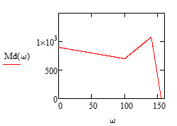
Figure 5 - Mechanical characteristics of |
МN – torque on the shaft of the pump;
qN – the maximum working volume of the pump;
f(q) – control parameter, -1 ≤ f(q) ≤ 1;
рa, p5 – pressure at the inlet and outlet of the pump, respectively;
аw - coefficient of hydro-mechanical losses, depending on the angular velocity;
аp - coefficient of hydro-mechanical losses, depending on the pressure;
а – constant hydromechanical losses;
Q5 – flow rate of working fluid at the outlet of the pump;
kyt – the coefficient of volume losses pump;
p5, p6 – the pressure at the inlet and outlet of the pipeline;
Q5, Q6 – working fluid flow at the inlet and outlet of the pipeline;
kpod.tr – compliance coefficient of pipeline with fluid;
l – coefficient of losses along the lengt;
ρ – density of fluid;
Ltr – the length of the pipeline;
dtr – diameter of the pipeline;
Counted options:
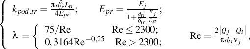
Еpr – reduced bulk modulus of elasticity of the pipeline with liquid;
Еj – modulus of elasticity of the liquid;
Еst – modulus of elasticity of the material of the walls of the pipeline;
dtr – thickness of the pipeline;
Re – Reynolds number;
νj – kinematic viscosity of the fluid.
Q6, Q7, Q8 – flow rates at the appropriate points of the throttle;
В – parameter accounting for the inertia of the liquid column;
μ – coefficient of flow, μ=ζ-0,5;
ζ – coefficient of hydraulic resistance;
fdr – flow section area of the throttle;
p7, p8 – pressure in the cylinder connection points;
Q7, Q8 –flow rates at the connection points of cylinder;
F7, F8 – the area of the piston in the respective cavities;
vsh – speed of moving stock on a glass cylinder;
Δv7, Δv8 – "dead" volume of the cavities;
L, Lmin, Lmax – current, minimum and maximum length of the cylinder (distance AB); L is determined by the relative positions of joined SMM, and Lmin и Lmax– cylinder design;
rC1, rC2 – the radius vectors of the centers of mass SMM 1 and 2 in KS OXYZ;
C',C'' – direction cosine matrix SK C1X'Y'Z' and C2X''Y''Z'', rigidly connected with the SMM 1and2 respectively, in the KS OXYZ, rigidly connected with the rock face;
vB-A – the velocity of point B relative to A in the SK OXYZ;
vC1, vC2 – velocities of the centers of mass SMM 1 and 2 in the KS OXYZ;
ω'1, ω''2 – angular velocities SMM 1 and 2 in the KS C1X'Y'Z' and C2X''Y''Z'' respectively;
h – damping coefficient;
Ftr0 – friction constant;
Cc,Cr – stiffness of completely shifted and completely split cylinder;
F1,F2 – reaction to the hydraulic cylinders attached to the SMM 1 and 2 in the KS OXYZ;
Counted options:
![]()
dp – piston diameter;
dsh7, dsh8 – diameter rod in the respective cavities;
The system of differential equations is solved with a Mathcad software using the Runge-Kutta method.
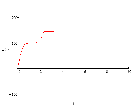
Figure 6 - Graphic dependence of the angular velocity |
Fig. 6 shows that the motor is accelerated with over 2,4 s.
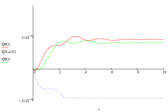 Figure 7 - Graphical dependence of flow at points 5,6,8 of time. |
If the equations are solved correctly, the flow rates in points 5 and 6 should be similar in magnitude and opposite in sign. To check this condition, we must integrate the flow of time.
![]() , m3/s;
, m3/s;
![]() , m3/s;
, m3/s;
The difference in the valuesflow rates 5 and 6 due to elastic expansion of the pipeline.
Fig. 7 shows that the initial time in points 6 and 8 rate is negative. This is due to the impact of G, while engine is accelerating.
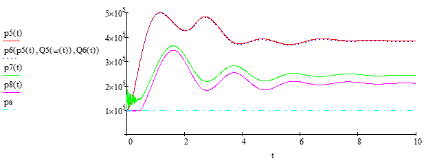
Figure 8 - Graphical dependence of pressure at points 5,6,7,8 of time. |
Pressure fluctuations at the point 7 (Fig. 8) due to the oscillatory system consisting of mass m2 and the cylinder with a liquid that acts as a spring.
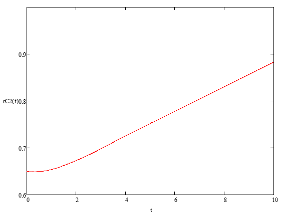
Figure 9 - Graphical dependence of the center of mass m2 of time. |
As a result of this work have been developed mathematical models to analyze the kinematic parameters of powered support, and a mathematical model of powered support and hydraulic drive systems based on functionally complete components that addresses the challenge of research, calculation and optimization of the powered supports. In the future, these mathematical models will be part of CAD to calculate the mining machines and systems..