INTRODUCTION
The hydroshock machines have wide area of distribution in mining business. The extensive range of application of hydroshock machines is caused by that such mechanisms are one of the basic sources of growth of all technological parameters. Most often hydroshock machines are used as an auxiliary part promoting more intensive destruction of mining breeds.
Besides hydroshock machines can be used as independent machines, being by the main technical element in process of chinks, destruction of oversized pieces of breed, etc. Various conditions of application, and also complexity of working processes in hydroshock machines have caused the large variety of the technical circuits and features of a design of hydroshock machines.
Generally, hydroshock machines represent pulse system with freely driven piston - brisk, moving between forging and top terminator, which can be both rigid, and elastic. Depending on an orientation of hydraulic influence it is possible to divide into the piston hydroshock machines on two basic groups:
Hydroshock machines of unary action with one working cavity of the cylinder, at which one course is brisk is made under action of a liquid, another - at the expense of force of a spring or body weight is brisk;
Hydroshock machines of double action, with two working cavities of the cylinder, at which reciprocating movement is brisk is provided with energy of a flow of a liquid without participation of springs.
The given division of hydroshock machines is rather generalized. So, in group of machines of unary action depending on a way of fulfilment of an active course is brisk the mechanisms of direct and return action are selected.
1 THEME’S ACTUALITY
On mines of Ukraine in the majority the electrical or pneumatic shock mechanisms are used. The installations with an electrical drive have the limited application on conditions of the safety precautions, and also because of low productivity. Lack of pneumatic shock installations is the low EFFICIENCY and large charge of the electric power
Last years the wide circulation was received by hydraulic shock devices having in comparison with pneumatic essential advantages, such, as higher EFFICIENCY, best noise-vibrating characteristics, opportunity of their application at absence of a pneumonetwork, large shock capacity at smaller weight. The hydraulic shock mechanisms are applied both manual, and portable. They can be useful and as the auxiliary tool to mechanization of manual jobs on destruction of oversized pieces of breed.
The jackhammers concern to manual mountain machines of shock action. They are intended for some minerals, and also for destruction of a firm ground, asphalt coverings. The experts mark mobility, autonomy, smaller weight and dimensions of hydraulic devices. They can be connected with the help of flexible hoses to any hydrosource, and also quite can work from hydrosystem of any road machine. All set of hydrotools, which work on object, can be connected through quick-detachable hydraulic connection to a uniform source of energy.
2 THE PURPOSE AND RESEARCH PROBLEMS
The purpose given master’s work is the establishment of laws and optimization of parameters of working process of hydroshock machines of manual action. For achievement of an object in view it is necessary to decide the following basic tasks:
- to consider and analyse existing manual machines of shock action with various drives;
- to lead the analysis of the basic parameters describing working process of a hydrohammer;
- to choose parameters of pump station for maintenance of high power parameters of a hammer;
- to choose parameters of pump station for maintenance of high power parameters of a hammer;
- to make imitating model and algorithm of its realization for PC;
- to choose rational parameters of a hydrohammer;
- to analyse constructed regressive model.
3 SCIENTIFIC AND PRACTICAL VALUE
The scientific meaning of work consists in expansion of representations about the theory of working processes of hydroshock devices, establishment of laws of working process of a hydrohammer, substantiation and choice of a range of rational parameters of the device from a condition of its maximal EFFICIENCY.
The practical meaning of work consists in development of imitating algorithm of working process of a hydrohammer and program for PC.
4 REVIEW AND COMPARATIVE ANALYSIS OF RESEARCH AND DEVELOPMENT RELATED
4.1 Overview of pneumatic shock devices
Hammer is a pneumatic piston machine impact of air distribution valve, working under the action of compressed air. The hammer consists of air distribution and impactor handles gathered in her starter. Air distribution-shock mechanism performs supply of compressed air into the cylinder barrel at a time in the chamber of the direct and reverses the impactor and the issuance of the exhaust air to the atmosphere, converting the energy of compressed air into mechanical work moved impactor.
4.1.1 The figure shows the structure of pneumatic jackhammer
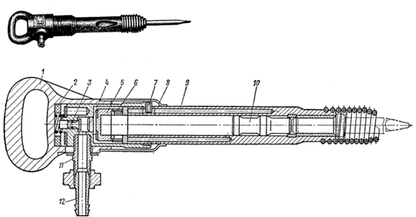
Figure 4.1.1 – Pneumatic jackhammers
Where 1 - Handle, 2 - a shock absorber, 3 - valve, 4 - cap 5 - box 6 - valve, 7 - lock, 8 - ring retainer, 9 - trunk, 10 - drummer, 11 - threaded, 12 - nipple.
All drills are performed in almost the same design scheme, and different length of the barrel and projectile. Reducing vibration in the modern drills is achieved by reducing the mass and diameter of the impactor, the use of the buffer chamber idling, installing the shock absorber, etc.
4.2 Overview of electric shock devices
Electric Hydraulic with catcher Rod EBGP1 designed for flush drilling inclined and horizontal boreholes with a diameter of 50 mm and a length of 2,2 m in rocks with a coefficient of strength up to f = 12.
Electric is an electric motor 1, the hydraulic drive 3, two hydraulic cylinders 4, 6 traverse the hollow spindle 7, which is inserted into bore rod, and the gearbox 8. A special feature is the special design of the electric spindle with crosshead to intercept bar that allows you to drill boreholes to the full depth (2,2 m) of one bar. With the help of flanges rigidly interconnected electric motor, gearbox and hydraulic drive.
Figure 4.2.1 show main type of the electric bor hydraulic interception rod.
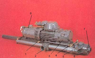
Figure 4.2.1 – Electric Bor Hydraulic with catcher Rod
4.3 Overview of hydraulic shock devices
Classification features developed hydraulic hammers devices. Most of the hydraulic hammers devices as a working fluid using technical oil or emulsion. The disadvantages of such liquids include pollution in possible leaks, fire hazards and the need for thorough cleaning. A special feature of hydraulic hammers devices developed in the Donetsk National Technical University, is used as a working fluid of technical water, which is an environmentally - and fire calls in its application to treatment only on the coarse solids. Select the type of switchgear. This classification attribute is inextricably linked with the previous one. Among the possible spools and valve distribution priority is given to the latter. This is because the valve switchgear compared with slide does not require high precision manufacturing executive body, a complex system of communication, high-purity fluid. Investigated hydro percussion devices operate in the self-oscillating mode. Valve distributor is made as a separate unit. Consequently, the principles of these devices are of the type - with rendered distributive mechanism. Select hydro percussion devices developed by the shock value of power. Depending on the magnitude of the shock power of N, developed by hydraulic hammers device conventionally distinguish hammers small shock power (N <2 kW), the average shock power (N = 2-10 kW) and a big shock power (N> 10 kW). Hammers low power shock characterized impact energy of 60 ... 100 J at a frequency of strikes 25 ... 15 Hz. Hydraulic hammers average shock power is mainly used as power units mine drill heads. It was determined that the same shock power (6 ... 8 kW) can be achieved in two ways: due to high energy (450 ... 600 J) at a low frequency of strikes (14 ... 10 Hz) or vice versa, due to the relatively low energy (120 ... 200 J) at a significant frequency of strikes (60 ... 20 Hz). Hammers great striking power used in the destruction of large oversize during open-cast mining or road construction. Given the analysis performed for follow-up study selected hammers small and medium-capacity Shock Valve switchgear, control cameras with forward and reverse moves, using as working fluid technical water.
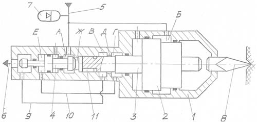
Figure 4.3.1 – The basic circuit of the hydroshock device with the controlled chamber of a direct course
5 MATHEMATICAL MODEL OF THE HYDRAULIC JACKHAMMER
Practical applications of hydraulic jackhammers to control the camera work of the constrained using simplified engineering methods of calculation, which does not fully take into account the peculiarities of the operating cycle and the factors influencing the formation of structural and operational parameters. In this regard, the work devoted to the development of mathematical models and methods of engineering calculation and justification of design and operational parameters of pneumatic breakers to control the camera work for the destruction of the building materials and rocks, is correct.
To study the dynamics of hydraulic jackhammers widely used mathematical modeling of full-cycle or the individual phases. Analysis of known mathematical models shows that they fully take into account the following factors: temperature and fluid properties, the value of clearances in mating surfaces of moving pairs.
The mathematical model takes into account the mass of the striker spool housing, the piston HPA, compressibility and temperature of the fluid, variable friction, the parameters of the pipeline, pressure-flow rate characteristics of the pump and allows you to simulate the work of hydraulic jackhammers different structures: the controllable camera working stroke, with a controlled camera reverse ; to control the camera and reverse travel of the casing, as well as with network or without batteries.
In developing the mathematical model, the following assumptions: all components and parts, except for pipelines, are absolutely rigid, power compression of the body to the hot environment constant, the fluid flow in pipes and canals turbulent.
The main links in modeling any of the schemes are as follows: node projectile, the piston-striker which makes reciprocating motion under the forces of pressure on its working surface and the dispenser unit, which provides self-oscillating mode. The equation of motion of the striker has the form:
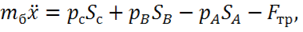
where  weight piston-striker; х – coordinate of the piston-striker position ; weight piston-striker; х – coordinate of the piston-striker position ;  - the fluid pressure in the respective working chambers; - the fluid pressure in the respective working chambers;  - surface area piston-striker in the respective chambers; - surface area piston-striker in the respective chambers;  - the friction produced by rubber seals (rings) piston-striker, is calculated by formula: - the friction produced by rubber seals (rings) piston-striker, is calculated by formula: 
In accordance with the classical theory of impact velocity after the collision with the instrument is given  in in  , in which R-factor of recovery speed, which may be in the range 0,1 ... 0,3. , in which R-factor of recovery speed, which may be in the range 0,1 ... 0,3.
Moveable element node is the distributor piston-valve, the equation of motion which has the form: 
Pressure in the chamber is calculated as:  , ,  , ,  , , – дthe pressure in the respective working chambers. Costs are determined by speed of motion of the piston-striker – дthe pressure in the respective working chambers. Costs are determined by speed of motion of the piston-striker  . .  – Hydraulic resistance of channels connecting the respective chamber – Hydraulic resistance of channels connecting the respective chamber  - A variable hydraulic resistance between the saddle and valve. - A variable hydraulic resistance between the saddle and valve.
The chamber pressure valve-distributor:  , ,  Here Here  - hydraulic resistance channel BE, - hydraulic resistance channel BE,  – variable hydraulic resistance between the head of the valve and seat from the overflow line, calculated by the formula – variable hydraulic resistance between the head of the valve and seat from the overflow line, calculated by the formula  , ,  – concentrated resistance overflow line. – concentrated resistance overflow line.  – Consumption, defined velocity of the dispenser valve, – Consumption, defined velocity of the dispenser valve,  - flow rate entering the waste line. The pressure in the chamber can be expressed as: - flow rate entering the waste line. The pressure in the chamber can be expressed as:  . .
The joint solution of all the above equations and is the basis of mathematical modeling workflow hydraulic hammering mechanism for review of the scheme.
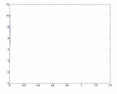
Figure 5.1 – The diagram of speed is brisk for a hydraulic jackhammer.
(animation: volume - 28,1 Кbyte; size - 451х364; consists of 10 frames; a delay between frames - 0,5 sec; a delay between last and the first frames - 2 seс; quantity of recycle - 10)
CONCLUSION
Experience with hydraulic hammers confirms their obvious advantages over pneumatic:
Providing high energochastotnyh indicators;
Ability to use as a working fluid of technical water, which is an environmentally - and fire calls in its application to treatment only on the gross solids;
Mobility, autonomy, less weight and dimensions of hydraulic equipment;
Increased efficiency;
Reduced operating costs;
Reducing noise and dust. It is now widely known hammers, used as the working fluid mineral oil. There is information about the possibility of some types of such equipment at water-oil emulsion. Comparison of the results of bench testing with the characteristics of modern hydraulic pneumatic tools for output and power consumption and efficiency shows a slight superiority of pneumatic tools for output and a serious loss of their efficiency.
The result is not advisable to apply the powerful, heavy and expensive compressor stations instead compact and much cheaper hydraulic stations. Thus, the development and widespread use of hydro for repair, construction, road, tunnel work is very promising.
LIST OF THE USED LITERATURE
1.Тимошенко Г.М., Яценко А.Ф., Селивра С.А. Гидравлический ударный механизм исполнительного органа буровых машин // Уголь Украины,-1984.-№11.-с.24-25.
2. Селивра С.А. Разработка гидравлических устройств ударного действия для разрушения горных пород. Дисс. … канд. техн. наук:05.05.06.-Донецк,1986.-194 с.
3. Яценко А.Ф., Селивра С.А., Коваленко В.И. Испытание экспериментального гидравлического устройства ударного действия //Изв.вузов. Горный журнал.-1995 - №7.-с.109-111.
4. Коваленко В.И. Разработка и обоснование рациональных параметров гидроударных устройств шахтных бурильных машин.: Автореф. Дис.канд. Техн. Наук. Донецк: ДПИ, 1996.
5.Петров Н.Г., Павлов А.С. Волновые процессы в гидросистемах ударных механизмов бурильных машин. - М.: Издательство «Наука», 1982.
6.Павлов А.С., Лурье И.Ф. О выборе ударного механизма гидравлической бурильной машины. Изв. Вузов. Горн. Журн., 1978, №1, с.110-115.
7. Селивра С.А., Яценко А.Ф. Основы моделирования рабочего процесса гидравлических систем ударного действия // Наукові праці ДонНТУ – Донецьк – 2001 – Вип..35 – с.154-158(Сер. Гірничо-електромеханічна)
8. Соколинский Б.В. Машины ударного разрушения (Основы комплексного проектирования).-М.: Машиностроение, 1982.-184с.
9. Гидравлические отбойные и бурильные молотки / В.Ф.Горбунов, Д.Н.Ешуткин, Г.Г. Пивень, Г.С.Тен.-Новосибирск: Наука, 1982.-93с.
10.Устименко Т.А. Обоснование структуры и выбор оптимальных параметров гидравлических отбойных молотков. Дисс. … канд. техн. наук:05.05.06.-Донецк, 1990.-204
Top |