
Tsibulka Vladimir
Abstract
Topicality
Coal is the most widespread fuel for thermal power plants, because it is the unique energy resource which Ukraine has.
Boiler optimum work is reached at maintenance of stoichiometric structure as air-fuel on all boiler torches. The uniformity adjustment of fuel delivery, now, is made by experts by secondary signs and is being broken at a mode change of boiler operation, that conducts to economic losses because of ablation of fuel, skews of a temperature field in a boiler etc. Therefore there is a problem of direct measurement of coal dust flow rates on a torch in an real time mode.
The flow meters based on sampling methods are actively applied to measurement of a coal dust flow rates all over the world. There are some methods of sampling, but the main is method ISO 9931 and method ASTM/ASME. These methods are based on test set selection from a pipe where the coal dust moves. It is necessary to mention the disadvantages: continuous mode of control parameter measurement, the necessity of regular replacement elements change, of maintenance staff an the need of power unit stop for assembly.
In the economic Ukrainian conditions, the flow meters based on methods of sampling are not widespread. Therefore there is the necessity of flow meter development, which would provide continuous measurement of a coal dust flow rate on steam boiler torches, being technological in installation, convenient in operation and, thus, having comprehensible cost.
My master’s project says about research of a pulverized fuel pipe flow meter, developed in CCDB "Turbulence" by Donetsk national university.
The basic advantages of the developed flow meter
The developed flow meter follows next requirements:
- Convenience in installation and operation;
- High reliability;
- Good parameters of accuracy (an error of 3 %);
- Rather low cost.
The developed device carries out following functions:
- continuous measurement of a coal dust flow rate on a boiler torch;
- the information display in a numerical type;
- a possibility of measurement results conservation for a prolonged period of time for conducting archive and the analysis;
- a possibility of automation signal use.
Fig.1. The technological diagram of a flow meter installation
1, 6 – the sorters of static pressure, 2 - a probe of full pressure, 3 - the thermometer, 4 - estruations, 5 – pulverized fuel pipe, Pst1 - the gauge of static pressure, Pd1 - the gauge of dynamic pressure, t - the thermometer, Pst1-Pst2 - the gauge of a difference between pressures, КАС - the switchboard of analog signals.
The measuring method is mentioned in Russian and Ukrainian variant of master’s abstract.
The block diagram of a flow meter is presented on fig.2. It includes four measuring channels: two channels of dynamic pressure measurement, the channel of temperature measurement and the static pressure measurement channel. Dynamic pressure in the meaning of differential manometer will be transformed in electric current signal and a current-pressure will be transformed to an electric signal in Volts. In the temperature measuring channel the resistance thermometer is used.
With the help of resistance-pressure converter the electric signal is received, which leads to a standard level by means of the normalizing amplifier. The static pressure gauge at once gives a signal of pressure.
Further electric signals of the measuring information through the switchboard of analog signals SАS move to АDC, there being transformed to a digital format and being entered into microcontroller MC. The microcontroller carries out the further processing measuring signals, calculates expense of a coal dust and gives out the result onto indication. Through interface RS485 it is also possible to connect both computer and microcontroller. It is necessary for detailed values reception of all measured parameters for dependences and charts plotting, as well as for saving and print of measuring results.
Рис 2. Block Diagram of the flowmeter with one measuring channel's sensors
Results of tests
In October, 2009 the flow meter assembly to one of Kurakhovskaya TPS boilers has been carried out.
Up to the present day the channel works without failures, despite the lack of purge. The typical chart of the dust expense statistics in a dust pipe is presented on fig. 3. The block was in a reserve, and then was involved into operation.
Fig. 3. The dust expense chart through a torch №15 of power units №4 by the block start-up
In November, 2009 the dust feeder №15 has been excluded from group for 4 hours and the productivity characteristic of it has been received. On fig.4 results of measurements with the developed flow meter are presented. There are also results of measurements by the weighting method, carried out on the dust pipe in 1999 by the adjustment of Kurakhovskaya TPS.
Рис. 4. Dependence of dust consumption from turns of dust feeders
The flow meter has shown working capacity in operating conditions at simple enough hardware ensuring. Operation of the channel has also shown a possibility of measurements realization without sampling, using pressure drop on an area between gate and estuations. The photo of the flow meter installed gauges is presented on fig.5.
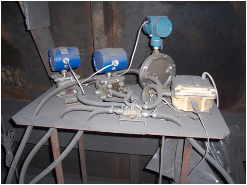
Fig.5. The block of gauges of the measuring channel
The abstract is composed from article basis, which at present is in publication process. My master’s project is a direct continuation of my baccalaur’s work. While writing abstract, master’s project is at an initial stage. Final completion: December, 2010. The full text of work and materials can be received from the author or from his scientific advisor in January, 2011.
Literature
- Кремлевский П.П. Расходомеры и счетчики количества. Справочник. 4-е изд., перераб. и доп. // Л.: Машиностроение, 1989., 701 с.
- ГОСТ 15528–86. Разновидности расходомеров и их преобразователей.
- ГОСТ 15528–86. Средства измерений расхода, объема или массы протекающих жидкости и газа. Термины и определения. // http://www.complexdoc.ru/scan/%D0%93%D0%9E%D0%A1%D0%A2%2015528-86
- ГОСТ 8.361–79. Расход жидкости и газа. Методика выполнения измерений по скорости в одной точке сечения трубы. // http://www.rst-s.ru/filemanager/download/23107
- Повх И.Л. Аэродинамический эксперимент в машиностроении. // Л.: Машиностроение, 1974, 480 с.
- Повх И.Л. Техническая гидромеханика. 2-е изд., доп. // Л.: Машиностроение, 1976., 504 с.
- Геращенко О.А., Гордов А.Н., Еремина А.К., и др. Температурные измерения. Справочник. Отв. Ред. Геращенко О.А. // АН УССР. Ин-т проблем энергосбережения. Киев. Наука. Думка, 1989., 704 с.
- Евтихиев Н.Н., Купершмидт Я.А., Папуловский В.Ф., Скугоров В.Н. Измерение электрических и неэлектрических величин: Учеб. Пособие для вузов. Под общ. ред. Евтихиева Н.Н. // М.: Энергоатомиздат, 1990., 352 с.
- Бабичев А.П., Бабушкина Н.А., Братковский А.М. и др. Физические величины: Справочник Под ред. Григорьева И.С., Мейлихова Е.З. // М.: Энергоатомиздат, 1991., 1232 с.
- Гутников В.С. Интегральная электроника в измерительных устройствах. 2-е изд., перераб. и доп. // Л.: Энергоатомиздат, 1988., 304 с.