Fault detection in internal combustion engines using fuzzy logic
Автор: M.B. Celik and R Bayir
Источник: http://www.ae-plus.com/Journals/1 Department of Automotive, Technical Education Faculty, Zonguldak Karaelmas University, Karabuk, Turkey
2 Department of Electronics and Computers, Technical Education Faculty, Zonguldak Karaelmas University, Karabuk, Turkey
Abstract: In this study, a complementary fuzzy-logic-based fault diagnosis system was developed to diagnose the faults of an internal combustion engine (ICE) and the system incorporated with an engine test stand. The input variables of the fuzzy logic classifier were acquired via a data acquisition card and RS-232 port. The rule base of this system was developed by considering the theoretical knowledge, the expert knowledge, and the experiment results. The accuracy of the fuzzy logic classifier was tested by experimental studies which were performed under different fault conditions. Using the developed fault diagnosis system, ten general faults which were observed in the internal combustion engine were successfully diagnosed in real time. With these characteristics, the system could easily be used for fault diagnosis in test laboratories and in service workshops.
Keywords: internal combustion engine, fuzzy logic, fault detection
1 INTRODUCTION
The wider use of automobiles and mass production increases demands for safe and reliable vehicles. Maintaining a high level of engine reliability by efficient fault diagnosis is thus important for several reasons. First, the downtime of the engine is expensive. Second, certain malfunctioning conditions can be a threat to the safety of both human beings and the environment. Accordingly, the large number of cars on the roads has led to legislative and regulatory pressures by certain nations, e.g. the USA and Japan, to control exhaust emissions [1]. Because of the power of the automobile, the running states of the engine will directly influence the automobile's working. There are many faults that arise from automobile engines; to clear these costs a large amount and much time has been spent with this aim [2]. Because of the inefficiency of burning in the engine or the failure of some systems, such as emission of the harmful carbon monoxide (CO),hydrocarbons (HCs), and nitrogen oxides (NO), fuel consumption increases and the engine power decreases. Determination of faults at the time that they occur and repairing them before they lead to larger faults is important to reduce the damage caused by engine faults that affect people, the economy, and the environment. The faults in automobile engines may be due to various reasons. Several engine faults may occur as a result of wear, without adjustment or malfunction of some engine parts. The engine faults may be termed intermittent failure or permanent failure. Dirty fuel, moisture in the distributor cap, and a high-voltage leak in the ignition system components can be given as examples of intermittent failure, while an air leak into the intake manifold, a defective spark plug, and worn carburetor jets can be given as the examples of permanent failure. Deviation from the expected behaviour might indicate probable faults in early stages and such faults are termed incipient faults. The incipient faults may gradually aggravate and ultimately lead to a major fault or permanent failure [3].
Today, artificial intelligence technology is widely suggested for the diagnosis of faults [4]. Several studies were performed to detect faults in engines using fuzzy logic which is an artificial intelligence technique. Soliman etal. [5] investigated the diagnosis of an automotive emission control system using fuzzy inference. Their results showed that the application of a fuzzy logic system can enhance the performance of an automotive diagnostic tool. Laukonen et al. [6] investigated fault detection and isolation for an experimental internal combustion engine via fuzzy identification. The results of this study showed how to construct a fuzzy identifier to estimate the engine signals necessary to calculate the deviation from nominal engine behaviour. This enabled the determination of certain actuator and sensor calibration faults. Kilagiz et al. [7] investigated a fuzzy diagnosis and advice system for optimization of emissions and fuel consumption. Because of the system, many engine faults were detected effectively.
Rauma et al. [8] investigated an approach using fuzzy logic in engine fault diagnosis. Their results show that faults can be detected with a fuzzy model and localized with inverted fuzzy models. Isermann [9] investigated the fuzzy logic applications for automatic control, supervision, and fault diagnosis. The results showed how fuzzy logic approaches can be applied to process supervision and to fault diagnosis with approximate reasoning for observed symptoms. Comly et al. [10] investigated engine fault diagnosis using fuzzy logic. With the fuzzy inference test bed, they investigated very-high-speed fuzzy logic to isolate faults using static information and early fault information that evolves rapidly in time. Lu et al. [11] investigated a fuzzy system for automotive fault diagnosis. The fuzzy model was implemented into a fuzzy diagnostic system that detected the vacuum leak in the electronic engine controller in automobiles.
Generally, most engine faults occur when the engine is running under load. When the engine is idling, some engine faults do not appear. For example, while the engine is at idle, the spark plug ignites but under load it may not ignite, or an engine with good ignition timing at idle may not be in good ignition timing at a high speed or heavy load. For correct and early fault diagnosis, fault detection should be performed when the engine is under load.
To effect this, an engine test system was developed in this study. This system enabled the engine to be loaded and the data to be transmitted to a computer simultaneously. The engine was run under the conditions susceptible to faults using the developed system. Many parameters which are deflected from normal values were monitored while the engine was running. In addition, a fuzzy logic fault diagnosis system connected to the engine test stand was developed in order to detect the faults in real time. In this study, the numbers of detectable faults as well as the reliability of the detection system were increased by measuring eight different internal combustion engine parameters. The organization of the paper is as follows. In section 2, the faults observed in the engine are introduced. The experimental studies used to detect these faults and to create the rule base are explained. In section 3, the developed fuzzy logic classifier model which was designed in the MATLAB fuzzy inference system editor is introduced. The rule bases are explained. In section 4, the results of this study and the suggestions about future studies are given.
2 EXPERIMENTAL WORK
An experimental set-up was constructed in order to build the rule base of the fault diagnosis system. It also served to detect the faults in real time while the engine was running under load and to test the fuzzy logic fault diagnosis system. The experimental set-up consists of a test engine, a d.c. dynamometer, a fuel flow meter, an exhaust gas analysis system, various measuring equipment, a personal computer (PC) and a data acquisition card, as shown in Fig. 1. An Advantech perripheral component interconnect (PCI) 1710 HG data acquisition card was used to transmit the data to the PC from the engine test stand. This card has a 16-channel analogue input and two-channel analogue output ports. The analogue input and output channels have 12 bit resolution. The sampling rate of the card is 100 ksamples/s. The card is quite fast since it works on the PCI slot and has 4 kB of cache memory. These features make it possible to measure complex and noisy signals [12].
While the engine torque, engine speed, engine temperature, and fuel consumption values were transmitted to the computer through the data acquisition card in real time, the CO, HC, carbon dioxide (CO2), and oxygen (O2) emissions and the l (excess air ratio) values were transmitted to the computer using RS-232 in real time. The emissions and l values were measured from the entry of the first exhaust silencer with a Sun MGA 1200 exhaust gas analyser. Fuel consumption was measured using the fuel flow sensor.
This test system was developed for a Fiat engine (1.6 l). The specifications of this engine are given in Table 1. All the tests were carried out on this engine. The engine working under load has more susceptible faults. Therefore, the tests were performed at a certain engine speed (3000 r/min), which acquired
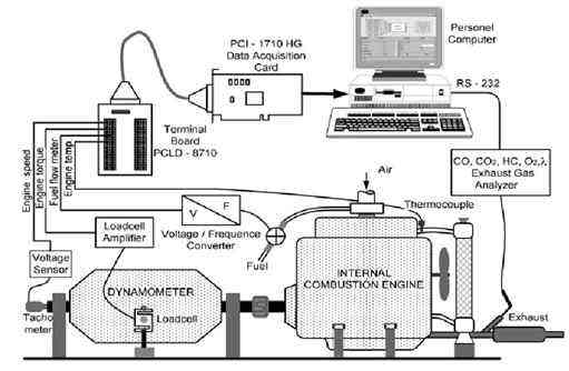
Fig. 1 Experimental set-up
Тable 1 Specifications of the test engine
| Item | Test engine |
| Make | Fiat 1,61 |
| Engine | Four stroke, four cylinder |
| Bore | 86mm |
| Stroke | 67mm |
| Compression ratio | 9,2 / 1 |
| Maximum power | 62 kW (5750 r/min) |
| Maximum torque | 130 N m (3000 r/min) |
| Power at maximum torque | 40 kW (3000 r/min) |
| Ignition system type | Transistorized coil |
| Fuel system type | Carburettor |
| Cooling system | Water cooled |
maximum torque at full load according to the engine catalogue value. Engine performance parameters such as the engine power, fuel consumption, and engine temperature at this speed were determined from the service catalogue of the engine [13]. The engine was tuned up before the tests and measurements were conducted when the engine reached the working temperature. For all the experimental work, the ambient temperature was kept constant at 20 °C without affecting the diagnosis results.
Table 2 Engine faults taken into consideration
| Number | Fault type |
Probable source of fault (defective systems and/or components) |
| 1 | Internal combustion engine normal | No fault |
| 2 | Lean mixture | Fuel system, air leak at intake manifold |
| 3 | Very lean mixture | Fuel system, air leak at intake manifold |
| 4 | Rich mixture | Fuel system, clogged air |
| 5 | Very rich mixture | Fuel system, clogged air |
| 6 | Faulty atomisation | Carburettor, intake system |
| 7 | Faulty ignition |
Ignition system components, incorrect ignition timing |
| 8 | Low compression |
Worn engine components |
| 9 | Excessive friction |
Lubrication system, rotated engine components |
| 10 | Overheating |
Cooling system, very lean mixture |
| 11 | Fuel system leakage |
Fuel system components |
Initially, the data were acquired from a healthy running engine at the predetermined conditions. Then, different faults according to Table 2 were physically induced in the engine and the data were measured with ten different faults. All the data for the engine torque, engine speed, fuel consumption, engine temperature, CO, HC, CO2, and O2 emissions, and l values were collected. For all tests, the values were recorded after allowing sufficient time for the engine to stabilize. The measured data were used for fuzzy logic to recognize the faults, and to discriminate between faulty and normal operation. Since the CO, HC, CO, and O emissions were sufficient to examine the combustion-related faults, NOx was not measured in this study. A flow chart indicating the stages of the fuzzy logic fault diagnosis system is given in Fig. 2.
3 DESIGN OF THE FUZZY LOGIC-BASED FAULT DETECTION SYSTEM
Fuzzy logic has found wide application. Electrical home appliances, automobile electricity, machines used daily, production engineering, industrial technologies, and automation are some of these applications [14]. Fuzzy logic makes use of the knowledge of experts which is possible through its transformation into linguistic terms. The accuracy of the formulation can be determined during the testing of the system or during real-time working by observation. This feature provides major flexibility for fuzzy logic. In this way, it has been effectively used in the studies of engine fault diagnosis and analysis. The only drawback of fuzzy logic is that it does not give definite results. These results are from its natural structure [15, 16].
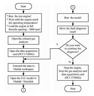
Fig. 2 Fuzzy logic fault diagnosis system flow chart (FLC, fuzzy logic classifier)
Fuzzy logic is a rule-based system that successfully combines fuzzy set theory with the inference capability of human beings. As rules, linguistic terms are used and are modelled through membership functions that represent simulation of the comprehension of an expert. Membership functions give the scaled value of definite number values that are defined by linguistic labels. Rules are defined such as IF (condition) THEN (result). The conditions and results are linguistic terms that represent the input and output variables respectively. The rule base of the fuzzy logic classifier consists of many rules. A rule base is used to obtain a definite output value according to the input value. The simplest fuzzy logic controller is given in Fig. 3.
In the fuzzy logic controller, x is the input value, m(x) is the fuzzified output value, m(u) is the result of the inference operation, and u is the output value. The fuzzifier unit converts definite data in the input of the controller to the format of linguistic variables. The fuzzy knowledge base represents two basic data: the database and the rule base. While the database includes definition of each system variable using the fuzzy set, the rule base covers inspection rules that are necessary to obtain a real output. The inference unit is a unit that performs fuzzy inference on fuzzy rules. This unit performs the operation resembling the way that people think. The defuzzification unit converts the fuzzy values obtained from the output of the inference unit to numerical values. This operation is called defuzzification.
Figure 4 gives a flow chart showing the fuzzy logic classifier design. The most important feature in the stage of fuzzy logic classifier design is that membership functions representing input and output parameters should be selected in a way that can absolutely define the system [17]. The input variables defined for this study and the membership functions of them are given in Fig. 5 while the output variables are given in Fig. 6. Taking engine faults into consideration, the fuzzy logic system consisted of eight inputs and eleven outputs. The engine power, fuel
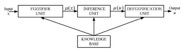
Fig. 3 Fuzzy logic controller
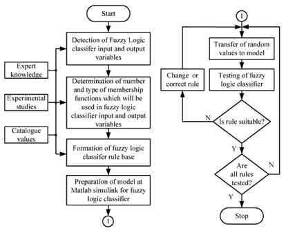
Fig. 4 The flow chart of the fuzzy logic classifier design
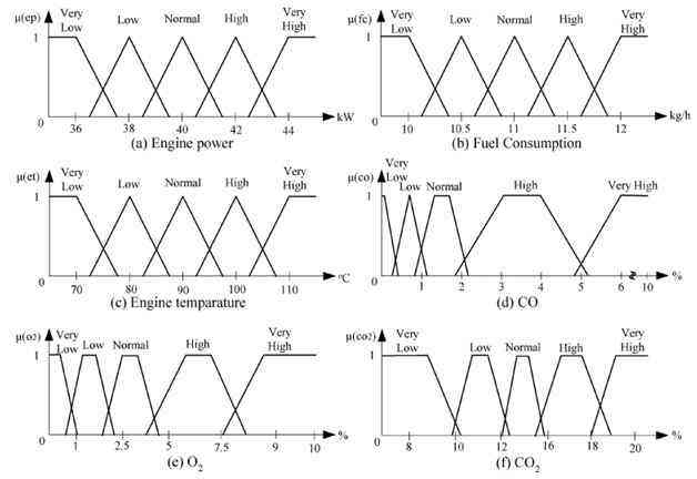
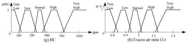
Fig. 5 Input variables of the fuzzy logic classifier for the Fiat engine (1.6 l)
Fig. 6 Output variable of the fuzzy logic classifier for the Fiat engine (1.6 l) (VLM, very lean mixture; LM, lean mixture; RM, rich mixture; NRM, normal; VRM, very rich mixture; FA, faulty atomization; LC, low comparison; FI, faulty ignition; EF, excessive friction; OH, overheating; FSL, fuel system leakage)
consumption, engine temperature, CO, O2, CO2, and HC emissions, and l were selected as the input variables. Each input variable consists of five membership functions. These functions are in the form of very low, low, normal, high, and very high. Each membership function of the output variable indicates a single fault. Triangle and trapezoid shapes were selected for membership functions of the input and output variables. The reason for the selection of va triangle membership function was to make the calculations in the fuzzification process and to enable the fuzzy logic classifier to give a quick response. The reason for the selection of the trapezoid is that the fuzzy logic controller does not necessitate calculations for the central area of the trapezoid. In addition, the trapezoid contains the best represented values of the defined membership function of this area. While some membership functions of the input variables were placed at equal intervals, some others were placed at different intervals. They were placed at different intervals according to the engine catalogue values, expert knowledge, and the results of the performed experimental studies.
When a fault occurs in an engine, some values of the engine parameters deviate from normal values.
Таблица 3 База правил
|
Engine power |
Fuel consumption |
Engine temperature |
CO emission |
HC emission |
emission CO2 |
O2 emission |
Excess air ratio |
State of internal |
| 1 | Normal |
Normal |
Normal |
Normal |
Normal |
Normal |
Normal |
Normal |
No fault |
| 2 | Normal |
Low |
Normal |
Low |
Low |
Low |
High |
High |
Lean mixture |
| 3 | Low |
Very low |
Very high |
Very low |
Very high |
Very low |
Very high |
Very high |
Very lean mixture |
| 4 | High |
High |
Normal |
High |
High |
Low |
Low |
Low |
Rich mixture |
| 5 | Low |
Very high |
Normal |
Very high |
Very high |
Very low |
Very low |
Very low |
Very rich mixture |
| 6 | Normal |
Normal |
Normal |
High |
Normal |
Low |
High |
Normal |
Faulty atomisation |
| 7 | Very low |
Normal |
Normal |
Normal |
Very high |
Low |
High |
Normal |
Faulty ignition |
| 8 | Low |
Normal |
Normal |
High |
Very high |
Low |
Low |
Low |
Low compression |
| 9 | Low |
Normal |
High |
Normal |
Normal |
Normal |
Normal |
Normal |
Excessive friction |
| 10 | Very low |
Normal |
Very high |
Normal |
Very low |
Normal |
Low |
Normal |
Overheating |
| 11 | Normal |
High |
Normal |
Normal |
Normal |
Normal |
Normal |
Normal |
Fuel system leakage |
in some fault diagnosis studies [18]. In the case of intersection of membership functions, the system indicates more than one fault.
It becomes possible to diagnose many engine faults through the measurements of engine exhaust emission values and some performance parameters. Whether there is a fault especially in the fuel and ignition system can be determined by analysing the emission values [19]. CO, O2, CO2, and HC emissions vary for different engines. Figure 7 shows typical variations in emissions with air-fuel ratio for a spark ignition engine [20, 21]. In this study, many input
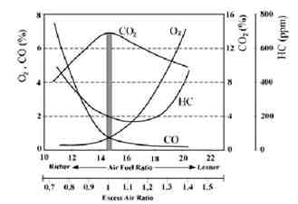
Fig. 7 Variations in some emissions in a spark ignition engine
variables were measured and variations in more than one variable indicate the same fault. Therefore, more accurate fault diagnosis was effected. For example, low engine power and fuel consumption together with low CO and CO emissions and high O2 emission and l indicate a lean mixture fault. In addition, detection of the real cause of the fault is possible by measuring many input variables. For example, overheating in an engine can especially result from the cooling system and/or a very lean mixture. If l and the CO, CO2, and O2 emissions of the engine are normal, the fault could result from the cooling system.
The fuzzy logic classifier model developed using MATLAB Simulink for fuzzy logic fault diagnosis is shown in Fig. 8. In this model, input variables were transferred from the MATLAB working environment to the fuzzy logic classifier. Fuzzification was performed according to the number of membership and the type of membership function selected by the fuzzy logic classifier. Fuzzy values (with the rules defined by an expert and using fuzzy logic operations), output membership functions, and values of membership functions were obtained. The user is then informed of the obtained fault diagnosis (Fig. 9).
The user can change the number of input and output variables of the fuzzy logic controller and limit the values of membership functions in the
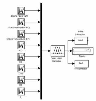
Fig. 8 The model developed in MATLAB Simulink for fuzzy logic fault diagnosis

Fig. 9 Diagnosis result window of the fuzzy logic fault diagnosis system (ICE, internal combustion engine)
MATLAB fuzzy inference system editor and can add rules to the rule base or can change the existing rules. In the fuzzy inference system editor, the shape and the number of membership functions of input and output variables can be changed. These features give flexibility to fuzzy logic fault diagnosis and provide clearer results.
4 CONCLUSIONS AND SUGGESTIONS FOR FUTURE STUDIES
In this study, a fuzzy-logic-based fault diagnosis system detecting engine faults was developed. As engines are more susceptible to faults during running at load, the fault detection was performed while the engine was running under a certain load. By using the developed system, ten faults observed in the internal combustion engine were successfully detected. The fuzzy logic fault diagnosis system was tested using a total of 86 data (concerning different faults) (Table 4). The fuzzy logic classifier was found to classify the data with 90 per cent accuracy. With these characteristics, the system could easily be used in service workshops for fault diagnosis and to test the performances of engines in laboratories. The reason for the 10 per cent fault can be attributed to the fact that the engine showed another fault when it was run under similar fault conditions. For example, an engine running with a very lean mixture can exhibit a lean mixture property. If the air-fuel atomization in the engine is not good, the engine may show a rich mixture property.
The developed system can be used for other engines having different specifications by adapting them to the test unit. These engines can be either other examples of the same design or other types of specifications. Some changes should be made in the rule base as the boundary values of fault diagnosis system input variables change in these engines. For example, performance parameters such as the engine power, fuel consumption, and emission parameters vary when the engine displacement, fuel system type, and ignition system type are changed. When fault diagnosis for these engines is required, redetermination of the boundary values of the input variables and alteration of the rule table by catalogue values, expert knowledge, and experimental studies becomes necessary. If fault diagnosis on an aged engine is to be performed, the fuzzy logic fault diagnosis system indicates that the engine is aged (low-compression fault). If this aged engine has other faults, these faults can also be diagnosed.
This system can be further improved by personalizing the general faults. For example, by investigating only the ignition or fuel system faults, the defective element can be detected. Also, sensor faults can be detected in internal combustion engines with electronic management systems by comparing the sensor signals of normal and defective engines. By changing the rule base and increasing the numbers of input variables, more faults can be detected. The developed system can be converted to
Table 4 Fault diagnosis results
| № | State of internal |
Number of |
Correct |
Wrong |
Result of wrong |
| 1 | Normal |
8 |
8 |
0 |
|
| 2 | Lean mixture |
7 |
6 |
1 |
Very lean mixture |
| 3 | Very lean mixture |
12 |
10 |
2 |
Lean mixture |
| 4 | Rich mixture |
9 |
8 |
1 |
Normal |
| 5 | Very rich mixture |
8 |
6 |
2 |
Rich mixture |
| 6 | Faulty atomisation |
9 |
8 |
1 |
Rich mixture |
| 7 | Faulty ignition |
7 |
6 |
1 |
Low compression |
| 8 | Low compression |
5 |
4 |
1 |
Faulty ignition |
| 9 | Excessive friction |
6 |
6 |
0 |
|
| 10 | Overheating |
7 |
7 |
0 |
|
| 11 | Fuel system leakage |
|
|
|
|
Total |
|
86 |
77 |
9 |
|
Amount (%) |
|
100 |
90 |
10 |
|
an appropriate tool for fault diagnosis with a chassis dynamometer or road test without removing the engine from the vehicle.
ACKNOWLEDGEMENTS
This research was supported by Zonguldak Karaelmas University Research Fund, under Project 2003-3802-02. The authors thank Zonguldak Karaelmas University and Karabuk Fiat Service for their contribution.
REFERENCES
- Gelgele, H. L. and Wang, K. An expert system for engine fault diagnosis: development and application. J. Intell. Mfg, 1998, 9, 539-545.
- Weijie, W., Yuanfu, K., Xuezheng, Z., and Wentao, H. Study of automobile engine fault diagnosis based on wavelet neural networks. In Proceedings of the Fifth World Congress on Intelligent control and automation, Hangzhou, People's Republic of China, 15-19 June 2004, pp. 1766-1770.
- Kher, S., Chande, P. K., and Sharma, P. C. Automobile engine fault diagnosis using neural networks. In Proceedings of the IEEE Conference on Intelligent transportation systems, Oakland, California, USA, 25-29 August 2001, pp.492-495 (IEEE, New York).
- Bay, O. F. and Bayir, R. Kohonen network based fault diagnosis and condition monitoring of pre-engaged starter motors. Int. ]. Automot. Technol., 2005, 6(4), 341-350.
- Soliman, A., Rizzoni, G., and Kim, Y. W. Diagnosis of an automotive emission control system using fuzzy inference. Control Engng Practice, 1999, 7(2), 209-16.
- Laukonen, E. G., Passino, K. M., Krishnaswami, v., Luh, G. C., and Rizzoni, G. Fault detection and isolation for an experimental internal combustion engine via fuzzy identification. IEEE Trans. Control Systems Technol., 1995, 3(3), 347-355.
- Kilagiz, Y., Baran, A., Yildiz, Z., and Cetin, M. A fuzzy diagnosis and advice system for optimization of emissions and fuel consumption. Expert Systems Applic., 2005, 28, 305-311.
- Rauma, T., KurId, M., and Alahuhta, P. An approach of using fuzzy logic in fault diagnosis. In Proceedings of the Fourth European Congress on Intelligent techniques and soft computing (EUFIT '96), 1996, Part 3, pp. 1909-1913 (Verlag der Augustinus Buchhandlung, Aachen)
- Isermann, R. On fuzzy logic applications for automatic control, supervision, and fault diagnosis. IEEE Trans. Systems, Man, Cybernetics, Part A: Systems Humans, 1998, 28(2), 221-235.
- Comly, J. B., Bonissone, P. P., and Dausch, M. E.
Fuzzy logic for fault diagnosis. Proc. SPIE, 1991, 1381, 390-400. - Lu, Y., Chen, T. 0., and Hamilton, B. A fuzzy system for automotive fault diagnosis: fast rule generation and self-tuning. IEEE Trans. Vehicular Technol., 2000, 49(2), 651-660.
- PCI-171O series user's manual, 2003 (Advantech Co.
Ltd, Taiwan). - Fiat Tempra service catalogue, 1990 (Kaya Press, Istanbul) .
- Mendel, J. T. Fuzzy logic systems for engineering: a tutorial. Proc. EEE, 1995, 83(3), 345-377.
- Chow, M. Y. Methodologies of using neural network and fuzzy logic technologies for motor incipient fault detection, 1997 (World Scientific, Singapore).
- Kalogirou, S. A. Artificial intelligence for the modeling and control of combustion processes: a review. Prog. Energy Combust. Sci., 2003, 29, 515-566.
- Lee, C. C. Fuzzy logic in control systems: fuzzy logic controller - Part 1. IEEE Trans. Systems, Man, Cybernetics, 1990, 20(2), 404-418.
- Bay, O. F. and Bayir, R. Fault diagnosis of starter motors using fuzzy logic. In Proceedings of the Third International Advanced Technologies Symposium, Ankara, Turkey, 2003, pp. 520-534 (Gazi University).
- Crouse, W. H. and Anglin, D. L. Automotive mechanics, 1993, p. 476 (McGraw-Hill, New York).
- Heywood, J. B. Internal combustion engines fundamentals, 2000, p. 147 (McGraw-Hill, New York).
- Ferguson, C. R. Internal combustion engines, 1986, p.404 (John Wiley, New York).