Seismic Processing 9: Wavelet Transforms
Wavelet transforms for seismic data processing
Douglas J. Foster* and F. David Lane, Mobil Exploration and Producing Technical Center
Charles C. Mosher, ARCO Exploration and Production Technology
Ru-Shan Wu, Institute of Tectonics, University of California, Santa Cruz
Summary
Considerable attention has been focussed on the use of wavelet transforms for seismic data compression. In addition to data compression, wavelet transforms also provide a powerful tool for analysis and processing of seismic data. In the frequency domain, wavelet transforms can be expressed as pairs of low and high pass filters that are repeatedly applied to a seismic trace. Using this framework, geophysical operations such as noise suppression and wave propagation can be readily derived for the wavelet domain. A unique feature of the wavelet transform is the availability of both time and frequency axes in the transform domain. Algorithms that require simultaneous access to time and frequency, such as attenuation analysis, can easily be implemented in the wavelet domain. Dual access to time and frequency comes at price, however. The filters used to implement the transform overlap in the frequency domain, which leads to internal aliasing for many algorithms, including data compression. Careful attention to the details of the aliasing terms in the transform is crucial for effective algorithms. A promising area for future research is the use of wavelet transforms for compressing integral operators. As an example, we describe the Radon transform in the wavelet domain, which results in compression of both the data processed and the operations performed.
Introduction
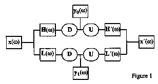
Wavelet transforms are often viewed as convolutional filter banks operating on a signal. Wavelet transforms can also be viewed as windowing functions in the frequency domain acting on the Fourier transform of the signal (Figure 1, after Vetterli and Herley, 1992). In this representation, x(ω) is the input signal, y0,1(ω) are the Fourier transforms of the filter bank outputs, L and H are Fourier domain filters, and D and U are Fourier representations of decimation and upsampling operators. In the Fourier domain, every other sample in a time domain signal can be set to zero by applying the folding operator
 ,
,
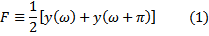
which causes the upper half of the spectrum to alias into the lower half (Figure 2, after Mosher and Foster, 1995).
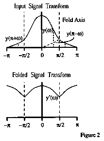
Inverse Fourier transformation over half the original interval results in a decimated signal, where every other sample has been removed. Upsampling can be accomplished by unfolding the spectra in the frequency domain, followed by an inverse Fourier transform over twice the original interval. Given these definitions, straightforward filter analysis provides conditions on the filters for exact reconstruction of the input signal:


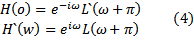
These equations are known as the normalization and aliasing conditions in the wavelet literature (Vetterli and Herley, 1992). The aliasing condition (Equation 3) requires that the aliased portions of the filtered signals cancel. Note that any operation in the wavelet domain that does not satisfy Equation 3 will result in aliased energy appearing in the output signal.
Orthogonal filter banks that satisfy Equations 2 and 3 are often constructed by setting
known as a QMF or Quadrature Mirror Filter in the literature (Meyer, 1993). Most of the commonly used wavelets (i.e. Daubechies, 1992) are Finite Impulse Response (FIR) filters that satisfy Equation 4. These filters have compact support in the time domain, which is a highly prized feature of wavelet transforms for space-time operations.
For some classes of geophysical operations, compact support in the frequency domain is a desirable feature. Finite Frequency Response (FFR) filters can be constructed with orthogonal window functions that satisfy Equations 2-4. An obvious choice are sine and cosine windows (Mosher and Foster, 1995), illustrated in Figure 3. These functions can be used to
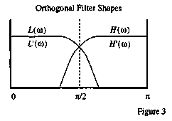
design custom wavelets for geophysical operations, and provide a convenient framework for studying and understanding the effects of aliasing in the wavelet domain. Figure 3 also shows why L and H are viewed as a pair of low-pass and highpass filters.
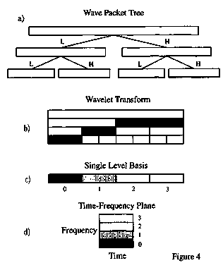
Wavelet transforms of various types are constructed by repeated application of filter banks that satisfy Equations 2 and 3. This operation produces a binary tree where the filtered signals are reduced in length by a factor of 2 at each successive level of the tree, illustrated in Figure 4a. If the high pass packets are retained, and the low pass packets are repeatedly filtered, a traditional wavelet transform is obtained, indicated by the shaded boxes in Figure 4b. Starting at the last level, the shaded packets can be repeatedly combined to recover the original signal. The number of samples retained in the "wavelet basis" is equal to the number of samples in the original signal. Note that as the tree grows, the set of combinations of packets that can be retained to provide a unique orthogonal wavelet representation also grows.
Time-Frequency Analysis
A "single-level wavelet basis" can be constructed by retaining a single row of packets from the tree, illustrated in Figure 4c. By viewing this row as a 2-dimensional matrix rather than set of 1-D vectors, a time-frequency plane can be constructed, illustrated in Figure 4d (after Wickerhauser, 1991). Wavelet time-frequency representations based on a unique orthogonal basis can be inverted to recover the original signal, unlike many other time-frequency analysis techniques.
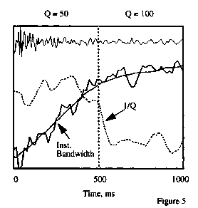
This provides a convenient domain for time-frequency operations, such as attenuation analysis, illustrated in Figure 5. In this example, a simple synthetic trace was computed by convolving a Gaussian reflectivity series with a band-pass wavelet for a constant velocity medium. Frequency domain spectral ratios were used to apply a simple constant-Q function that changed from 50 to 100 in the center of the model. A wavelet transform time-frequency plane was computed, and the bandwidth of the signal was estimated at each time sample. Figure 5 shows the seismic trace, the Q model, and the instantaneous frequency bandwidth at each time sample. Q is inversely related to the derivative of the bandwidth with respect to time, so an estimate of l/Q was obtained by differentiating a smoothed version of the instantaneous bandwidth. As shown, the wavelet time-frequency analysis provides a stable estimate of the changes in instantaneous bandwidth for this example.
Data Compression
The frequency domain representation of wavelet transforms provides a convenient domain for analyzing the effects of data compression in the wavelet domain. Seismic data are compressed by performing a multi-dimensional wavelet transform of an array of seismic data, followed by quantization (conversion to integers) and entropy encoding (a compression technique similar to those used to compress text files on computers). An example is shown in Figure 6, where a simple 2D zero-offset synthetic for a point diffractor was compressed by a factor of 20 and then restored. The figure shows the input point diffractor and the difference between the restored and original records (the difference section has been scaled up to highlight differences). Presentations on data compression often refer to residuals such as those seen in Figure 6 as "random noise left in the background". But since we started this example with a clean synthetic point diffractor, where did this "random" noise come from?
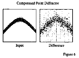
The answer is provided by Equation 3, the aliasing condition for invertibility of the wavelet transform. When the wavelet domain data are quantized, each wave packet is quantized independently. Round-off errors are different for each packet, so the aliased energy in one packet that is required to cancel abasing in the adjacent packet may be quantized differently, or even set to zero. As a result, aliased energy leaks through the inverse transform, leaving what looks like pseudo-random noise in the background. Design of data compression systems should include efforts to minimize the effects of aliasing.
Wave Propagation
A convenient starting point for the study of wave propagation is the dispersion relation for plane waves in a constant velocity medium. The frequency domain framework for wavelet transforms provides a means of obtaining wavefield extrapolators in the wavelet domain. As an example, consider extrapolation for 2D zero-offset data,
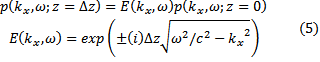
where the wavefield p in the Fourier domain is moved to the next depth level by the familiar phase shift extrapolator (Stolt and Benson, 1986, p.90).
For this example, we transform over the horizontal space coordinate, referred to as a "beamlet" transform:
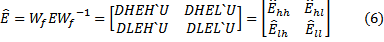
As might be expected, rather than an extrapolator that only deals with the low and high pass wave packets, the extrapolator also contains off-diagonal terms to correctly propagate the aliased portions of the transformed data. This analysis can be used to derive migration operators in the wavelet domain that correctly handle the full wavefield (Mosher, Foster, and Wu, 1996). This example further shows the importance of incorporating the aliasing condition in any operation performed in the wavelet transform domain.
Integral Operators
As the previous analysis of wave propagation shows, wavelet transforms can be used to manipulate geophysical operations. Given that wavelet transforms can compress seismic data, can they also be used to compress the number of operations performed? As an example, consider the Radon transform
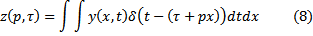
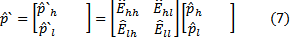
of an input signal y(x,t), and the discrete representation of a space-time domain wavelet transform of the input data
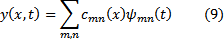
where cmn are the wavelet transform coefficients and ψ mn are the wavelet values. Substituting 9 into 8 yields a Radon transform in wavelet coordinates
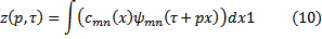
Since wavelets are known to provide sparse representations of seismic signals, the domain of integration can be reduced by a factor proportional to the data compression.
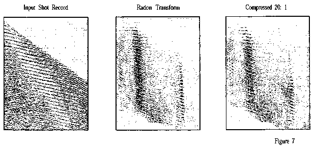
An implementation of a Radon transform using Equation 10 is shown in Figure 7. The input record was first transformed with no compression (i.e. a traditional slant stack), and then transformed using Equation 10, retaining only the top 5% of the wavelet coefficients (20: 1 compression). The results are nearly identical, reducing both computation and storage by a factor of 20.
Conclusions
Wavelet transforms provide a unique set of features that can be used to manipulate and enhance seismic data processing algorithms. These features include simultaneous access to time and frequency axes in the transform domain, and possibilities for compressing both the data used and the operations performed in algorithms implementing integral operators. The challenge for efficient and accurate implementation of algorithms in the wavelet domain is proper handling of the aliasing terms introduced by the wavelet transform. Seismic data processing algorithms that appear to hold promise for more efficient and effective implementation in the wavelet domain include noise suppression, time-frequency analysis, and seismic imaging.
Acknowledgments
The authors would like to thank ARCO and Mobil for their support of joint, cooperative projects in this area, and to David Campbell and Terry Young for their early support of wavelet transform research.
References
- Daubechies, I., 1992, Ten Lectures on Wavelets, SIAM
- Meyer, Y., 1993, Wavelets: Algorithms and Applications, SIAM
- Mosher, C. C., and Foster, D., J., 1995, Frequency domain representations of the wavelet transform, Mathematical Methods in Geophysical Imaging III, SPIE Proceedings Series
- Mosher, C. C., Foster, D., J., and Wu, R. S., 1996, Phase shift migration with wave packet algorithms, Mathematical Methods in Geophysical Imaging IV, SPIE Proceedings Series
- Stolt, R. H., and Benson, A. K., 1986, Seismic Migration Theory and Practice: Handbook of Geophysical Exploration Vol. 5, Geophysical Press.
- Vetterli, M, and Herley, C., 1992, Wavelets and filter banks: theory and design, IEEE Trans. on Signal Proc.
- Wickerhauser, M.V., 199 1, Lectures on wavelet packet algorithms, Washington University, Department of Mathematics Technical Report