
The object of research is the system power supply block and life of general voltage auxiliary power station, which has a large dispersion across the station and at a considerable distance from it.
The aim of research is to identify opportunities to connect to sections auxiliary power more dispersed load. Applied to study the station consists of the pumping process water and Dredge pumping the second lift, which now receive power from the city substations, which will improve reliability and efficiency of power plants.
Calculations of the current short-circuit modes of self-engines were carried out by means of mathematical modeling with the use of matrix methods to calculate the nodal multi-node schemes for solving differential equations group motors in the simulation group and their run-solving systems of nonlinear algebraic equations in the synthesis parameters of induction motors of own needs system. At this time Master's work is not finished.
Power plants is applied to study the reverse process water system with cooling towers tower. To refill the significant loss of service water recharge scheme implemented circuit of technical water from the reservoir. According to the project, pumping the water pump technical water is supplied from a network of substations. The scheme has insufficient power supply pumping reliability.
A similar situation was and Dredge the second lift pump, pumping ash slurry ash-disposal area at the plant. Pump is powered by two cable lines from the power substation. Due to the damage of cables laid on the rocky ground, power supply circuit of the pump has a low reliability.
In order to improve reliability and efficiency of these pumping stations in the studied power plant is designed to execute transfer of power from the auxiliary power system voltage of 6 kV. The objective of this study is to determine the technical conditions specified transfer power. To this end, we have studied the loading sections auxiliary power units, changes in the quantities of short-circuit conditions the self-electric auxiliary power unit under different conditions of their work, as well as the guidelines for building the relay protections.
Connecting to the sections auxiliary power units additional load should lead to a deterioration of the terms self-critical auxiliary mechanisms. To quantify the operating parameters for the self-electric motors, we calculated these modes on a PC program designed to package MathCAD.
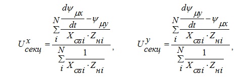
To calculate the multi-node scheme used the method of node voltages in a matrix form. His basic equation is:
where:
Uu — vector of unknown nodal voltages;
Yu — square matrix of nodal conductivities scheme;
Iu — vector of nodal currents.
Square matrix of nodal conductivities calculated by the formula:
The calculation formula for the vector of nodal currents Iu:
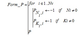
Matrix links the branches to the nodes of P may be formed from the known vectors of the initial numbers (N) and final (K) nodes of branches. For forming the matrix P using the following user function:
Process of self precedes the run-mode units. Distinguish between individual and group coasting motor. Reducing motor speed freewheel with an individual is under the action of the resistance mechanism. For each induction motor is determined by the new speed based on the solution of the basic equations of motion of the rotor:
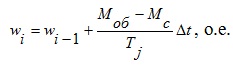
где Моб=0 — For the individual rundown;
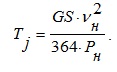
Mechanical time constant is determined by the known total moment of inertia of the unit and the nominal parameters given induction motor:
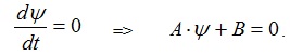
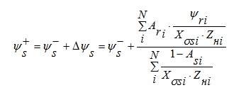
The initial value of flux linkage of stator and rotor are determined by the steady state in which the increment of flux linkages are zero:
The calculation is performed self-treatment based on the calculation of voltages in the nodes of the scheme and the solution of the basic equations of motion of the rotor. To obtain these voltages is advisable to use the method of nodal voltages.
Knowing the speed of each motor at the end of run-mode, and depending on the parameters of equivalent circuit of the slip and voltage on the section, we can determine the resistance of each motor, which takes part in a panel freewheel, as well as their general resistance. After that corrected the values in the matrix of nodal conductivities and calculated voltage on the section at the time of power restoration.
After determining the stresses in the scheme will begin immediately calculate the self-treatment.
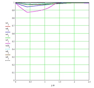
For the first step of calculating the self-values are taken speeds induction motor with the last step run-mode and the voltage of the method, the nodal stresses. The calculation is performed until all the engines did not reach rated speed, or time of self-will exceed the maximum allowed by the technological requirements of basic equipment.
Rotational speed at the beginning of coasting by the parameters of pre-damage mode is determined by the load factor of the unit and the known value of slip at rated speed [6]:
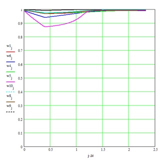
Results:
— successful self-starting electric motors with the increased complexity of the power circuit;
— satisfactory inspection of equipment and conductors under the terms of the short-circuit;
— introduction of an isolating transformer in the mains supply has reduced working to acceptable value earth fault currents, to avoid complicating the scheme because of the phase shift between the working and backup power supply;
— managed to keep the minimum number of degrees of selectivity over time.