


Relevance of the topic
The purpose of the work
Content of the work
Direction for further research
Introduction
ElectroMagnetic Compatibility (EMC) is one of the main requirements for power supply system. Overestimation of EMC leads to unnecessary increase investment, and understatement - to the detriment of the additional power losses, reducing the life of electrical equipment, deterioration of product quality. In this regard, high demands are imposed on the validity and accuracy of methods for estimating how EMC at the design stage and in the operation of power supply systems.
The problem with EMC in a sense analogous to the problem of environmental protection: the increasing power of the power consumers and the intensification of modes of their work lead to the distortion parameters of electric energy, which, in turn, negatively affects the modes of other power consumers of the network. Ensuring EMC associated with significant costs, giving rise to high demands for accuracy and validity of methods for assessing EMC in power networks.
The goals of the EMC are solved at the design stage and in operation, that requires the creation of methods of calculation and measurement of EMC - variables quantitatively characterizing the properties of EMC.
Relevance of the topic
The practical relevance lies in the fact that an objective assessment can reasonably choose the means to stabilize (EMC) and assess the impact of noise on electrical equipment.
Usually figures are calculated without taking into account the EMC dynamic properties of transformers, though they lag smoothing has an impact on noise. Development of methodology for assessing the EMC based transformer causes scientific relevance.
The proposed dynamic model of the transformer for the estimation of its impact on EMC, characterized in that study the instantaneous voltage at the output and input transformer.
The practical value lies in the fact that the proposed method allows to take into account the inertia of transformers in evaluating EMC.
The purpose of the work
The aim is to develop a dynamic model of the transformer and the evaluation of its impact on EMC.
Main research tasks:
- develop a methodology to account for the inertia of transformers;
- provide a dynamic model of the transformer.
Content of the work
In the literature [1] there are two equivalent circuit of the transformer: the sequences (Fig. 1a) and parallel (Fig. 1b) resistance in the branch of the magnetization. In this case, start from the constancy of resistances in the branches of the magnetization. Interturn capacity are not considered, since the frequency range does not exceed the value of 10000 Hz.
For the analysis of existing schemes of substitution studies were carried out as described in [2]. According to their results it was concluded that the analysis of processes of change of instantaneous voltage in the transformer must be used equivalent circuit with parallel connection of elements in the chain of magnetization, while setting the oscillation current voltages - a scheme with a serial connection.
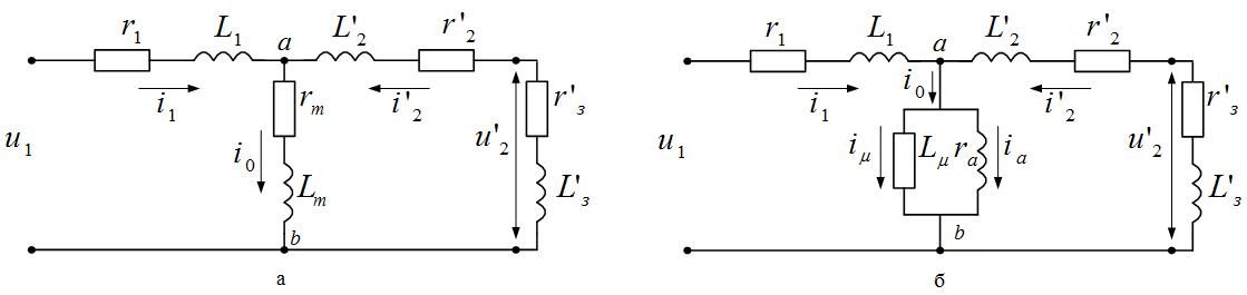
b - with parallel resistances in the branches of the magnetization
Also, it was determined that in general advisable to use circuit with an ideal transformer [3].
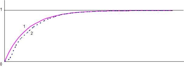
In conducting research analyzed the amplitude-frequency characteristics (AFC) of the transformer on the submitted schemes.
Supposed to replace the transformer RC-link, since the form of their transition functions h (t) - close to exponential. Such a replacement can significantly simplify the calculations.
Assessing the impact of harmonics on the transformer.
Voltage harmonics cause an increase in transformer losses and hysteresis losses due to eddy currents in the steel, as well as losses in the windings. Also reduces the life of isolation.
The increase in losses in the windings of the most important in the converter transformer, since the presence of a filter to attach normally to the side AC, does not reduce the current harmonics in the transformer. Therefore, the need to install a large power transformer. There are also local overheating of the transformer tank.
The negative aspect of the impact of harmonics on transformers is powerful in circulation tripled the residual current in the windings connected in a triangle. This may lead to overload.
Function of the output voltage u2(t), will look like:
where n - number of harmonics.
Assessing the impact of deviations of the voltage on the transformer.
Voltage tolerance - unlike the nominal value of the actual voltage, which is located in the established mode of operation of the electricity system.
Voltage deviation at this point in the network usually takes place under load, which corresponds to its schedule.
The impact of voltage fluctuation on the work of processing units: when the voltage level decreases, worsening of the process, but also increases its duration. Therefore it suffices to greatly increased production costs. When the voltage rises - is reduced during the life of the equipment and increases the likelihood of accidents. When there are large voltage deviation can occur disruption of the process.
Taken to record one-minute deviation, and it is quite slow. As a result, virtually no distortion.
Impact of fluctuations in voltage transformer.
Voltage fluctuations - the rapidly changing voltage deviation from the half-length up to several seconds. They occur under the influence of a rapidly changing network load.
Sources of voltage fluctuations are a powerful electrical receivers with a pulse, rezkoperemennym consumption patterns of active and reactive power: arc and induction furnaces, electric welding machines, electric starting.
Voltage deviation, exacerbated rezkoperemennym character, further reducing efficiency and equipment life. Cause the marriage goods. Contribute to disable the automatic control systems and equipment damage. For example, vibration amplitude and, to a greater extent, the phase voltages cause vibration motor driven tools and systems. In particular, it leads to a decrease in fatigue strength of pipes and reduce their service life. And when the amplitude of oscillations of more than 15% can be switched off magnetic starters and relays.
Distortion of the voltage curve may be caused by both external and internal factors. External distortions caused nesinusoidalostyu EMF generator power, as well as powerful non-linear loads on neighboring businesses. Sources of domestic distortions are powerful power-consuming equipment with non-linear current-voltage (thyristor converters, DSP, saturated magnetic systems, etc.). In experimental studies take into account the combined effect of external and internal distortions. In designing the power supply voltage is undistorted [4].
Because electricity is transmitted at a frequency f=50 Hz, the process of changing the current values ??of stress naturally represented as a sum of two components: sinusoidal uf(t) with a frequency of 50 Hz and nonsinusoidal
 ,
,
which we call a sine and a hindrance.
The question of allocation of sinusoids is a key to interpret the very concept of non-sinusoidal. Consider the case of a periodic disturbance with a duration cycle  s, which is superimposed on the sinusoid
 ,
,
with the carrier angular frequency  .
.
In the design, when given the graph interference, easily implemented, both interpretations of non-sinusoidal. The existing networks can provide a sine wave, if the voltage curve has a clearly defined areas of undistorted sinusoids. At those sites, as determined by any pair of ordinates sinusoid parameters remain unchanged. Nonsinusoidal component is defined as the difference between sine and noise. In the absence of undistorted areas the problem of separating sinusoids has no exact solutions. In this connection it is necessary to assess the impact on electrical equipment of the process u (t) or as a nonsinusoidal components tentatively accept the sum of higher harmonics, if the noise is periodic. Discrepancy between the nonsinusoidal component and the sum of higher harmonics evident, if a periodic disturbance has a duration of the cycle, which differs from 0.02 sec.
Typically, the duration tf integer m times placed on the expansion of the range, so the main quasiharmonics has a frequency m times less than 50 Hz. In solving problems it is necessary to consider all kvazigarmoiki, not only with frequencies that are multiples of 50 Hz. Otherwise, the score will be significantly understated EMC - more than most m different from unity.
The presence of voltage fluctuations essentially complicates the problem, since the modulation signal of 50 Hz leads to a distortion of the sinewave, even in the absence of noise sources with nonlinear volt-ampere characteristics. For example, if the network observed harmonic voltage fluctuations with the scale and frequency
λ Hz, the instantaneous voltage values are defined as follows for U=UН=1,  :
:
 ,
,where  - coefficient of modulation,
  – period of oscillations.
Direction for further research
It is planned on the basis of the proposed technique to develop a dynamic model of the transformer, to assess its impact on the EMC, as well as to determine the persistence of transformers.
In writing this essay master's work was not completed. The final version of the work available from the author or supervisor since December 2011.
Literature
- Кулик Ю.А. Электрические машины / Ю.А. Кулик. – М.: Высшая школа, 1971. – 456 с.
- Коваленко А.A., Куренный Э.Г. Выбор схем замещения трансформатора для анализа колебаний напряжения //Электротехника, электроника и микропроцессорная техника. - 2011.
- Курінний Е.Г., Дмитрієва О. М., Коваленко А.О. Динамічна модель трансформатора для оцінювання електромагнітної сумісності //Праці ДонНТУ (Інформаційний збірник). - 2010.
- Кузнецов В.Г., Куренный Э.Г., Лютый А.П. Электромагнитная совместимость. Несимметрия и несинусоидальность напряжения. – Донецк: «Норд-пресс», 2005. - с.157.
- ГОСТ 30372-95. Межгосударственный стандарт. Совместимость технических средств электромагнитная. Термины и определения. – Введ. 01.01.1997.
- ГОСТ 13109-97. Межгосударственный стандарт. Электрическая энергия. Совместимость технических средств электромагнитная. Нормы качества электрической энергии в системах электроснабжения общего назначения. – Введ. в Украине с 01.01.2000.
- Куренный Э.Г., Ковальчук В.М., Коломытцев А.Д. Оценка качества электроэнергии с использованием моделей объектов. – В кн.: Качество электроэнергии в сетях пром. предприятий. Материалы конференции. – М.: МДНТП, 1977. – С. 23-29.
- Шидловский А.К., Кузнецов В.Г. Повышение качества энергии в электрических сетях. – К.: Наукова думка, 1985. – 268 с.
- Шидловский А.К., Куренный Э.Г. Введение в статистическую динамику систем электроснабжения. – Киев: Наукова думка, 1984. – 271 с.
- Куренный Э.Г. Метод парциальных реакций для анализа процессов на выходе линейных фильтров в моделях электромагнитной совместимости / Э.Г. Куренный, А.П. Лютый, Л.В. Черникова // Электричество, 2006, № 10. – С. 11-18.
- CEI/IEC 61000-4-15. Electromagnetic compatibility – Part 4, Section 15: Flickermeter – Functional and design specification. 1997.
- Курінний Е.Г. Доза флікеру при періодичних коливаннях напруги / Е.Г. Курінний, О.М. Дмитрієва, В.О. Топчій // Праці Інституту електродинаміки Нац. академії наук України, 2009, вип. 22. – С. 123-129.