
One of the areas of development and modernization of equipment continuous casting machines (CCM) intended for subsequent production of sheet metal is to increase the maximum width and thickness of the cast on their slabs. At several metallurgical plants of foreign companies are now successfully operated CCM for slab widths up to 3250 mm. The thickness of the work piece can be from 150 to 355 mm [1].
The implementation of modern technology of continuous casting of steel at high CCM involves the use of slag-forming mixtures (SFM), admission in the mold to stabilize the operation of its mechanism of swing and improve the formation of sinterskin cast ingot [2].
Specified circumstances, and the need to reduce the number of attendants at the filling site of a new generation of CCM employed directly hand feed the SFM, determined the start of work on creation system of mechanized feeding of the SFM in the mold on the metal mirror at a rate corresponding to the rate of withdrawal of a continuous ingot. In most cases, a given mass flow rate of the SFM, introduced in powder or granular form, provided with moving along the mold screw feeder, which drives through frequency converters supply current can smoothly change speed and expendable features metering system [3].
The results of industrial tests developed at the department of mechanical equipment of ferrous metallurgy plants (MEFMP) Donetsk National Technical University (DonNTU) device for continuous feeding of the SFM in the mold for casting the slab cross-sectional dimension to 250 × 1800 mm confirmed the effectiveness of mechanized input mixture in comparison with the filing, is carried out manually by two caster [3]. Due to the uniform distribution of liquid slag layer on the perimeter of the mirror metal in the mold conditions improve interaction with its walls forming crust of the ingot to be stabilizing force its withdrawal and declining load fluctuations to the drive mechanism for rocking the mold, as well as reduced consumption of the SFM at least 15% [4]. However, the exploitation of a test sample dosing system allowed not only to identify "bottle neck" in its design, but also identify areas for further development of this class of devices. Their kinematics should provide for the desired period of time starting mixture dispersed across the free surface of the metal in the mold if it submerged nozzle, and the drive involved mechanisms — fit into the space bounded by the hull of the intermediate ladle and placed near the other equipment within the composition of the CCM. In this regard, studies related to improving the design and development of methods for calculating the geometrical and energy–power parameters of SFM dosing devices used in the production of slab pieces with large cross–section, are of great practical importance.
A device (figure 1) for dispensing the powdered slag-forming mixture on a mirror of the metal into the mold containing the feed bin, fitted in the lower part of his screw feeder, pneumatic proportioning system input dispensed material, and the nozzle, ensuring its uniform distribution on the free melt surface and placed at the exit end of screw feeder [5].
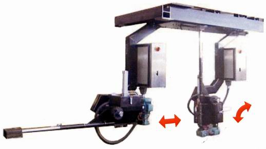
The disadvantage of this device is that it can be used to ensure the supply of slag-forming mixture only in the mold for casting billets of small section (profiled and bloom CCM). In this delivery system is to use two power sources: electric and pneumatic, which complicates its operation and maintenance. In addition, a la carte delivery of the mixture can not support the constancy of the required ratio of input material costs and the incoming liquid steel into the mold, which reduces the efficiency of slag-forming mixture.
Also known device for the continuous dosing of slag–forming mixture into the mold slab caster (figure 2), developed at the Department of MEFMP [2].
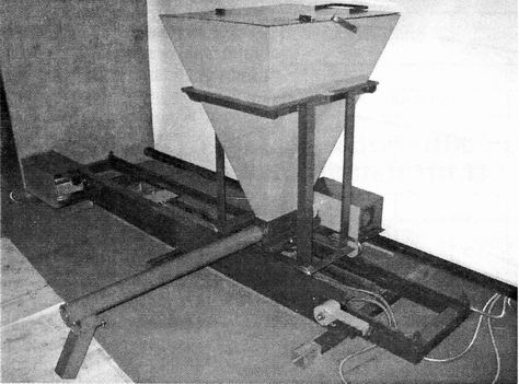
The device includes a mounted along the wide wall of the mold frame on which is installed cart that has the possibility of relative longitudinal movement with the drive and carrier feed bin, still mounted on it and fitted in the lower part of his screw feeder with a sloping feed toe.
The disadvantage of this device is that it works effectively for casting steel slab caster for billets with the boundary cross–sectional dimension 1800 × 250 mm. Using the device on the machines for the production of slab billets of large cross section is inefficient, because one truck, moving along the broad wall of the mold, tilting the feed screw feeder sock motion shall not speak of this wall inside the mold because of being in its cavity submerged nozzle. In this case, entered slag-forming mixture may fall on the mirror of the metal only in the zone adjacent to the toe near the pitcher to the mold wall, and large width of the slab is impossible to achieve uniform distribution of the mixture across its cross section. Besides, the invariable position of the longitudinal axis of the screw feeder at an angle of 90° makes it necessary for each case to set the length of the screw, which reduces the degree of universality of the device as a whole.
As a prototype for the design of dispensing the powdered slag–forming mixture on a mirror in a metal mold slab caster for billets of large cross-section made device for the continuous dosing of slag-forming mixture into the mold slab caster (figure 2), developed at the Department of MEFMP.
When you create a metering system designed for use in the production of slab billets, width and thickness is greater than 2 and 0,25 m, was adopted by the structural scheme (Figure 3), implying the existence of two screw feeders, the feed mixture separately in the mirror of the metal in the mold in a zone demarcated submersible glass. Moreover, each dispensing performs motion simultaneously in two directions — along and across the mold. This allows a greater uniformity of distribution of SFM all over the free surface of the mirror metal into the mold, slow moving trucks that are running dosing and reduce the size of feed bins.
Designed device (Figure 3) includes a frame 18, mounted along the wide wall of the mold 24 and provided with two guides 11 and 19, on which is based channel wheel 10 and 20, two trucks 17, with the possibility of longitudinal movement relative to the distance form 0,4 — 0,45 of the width of the slab, with a drive consisting of a self–locking worm gear motor 13, mounted on a shaft spur gear 14, located in engagement with rack 15. Rack rests on two rollers 16 and their ends pivotally connected with the cart 17.
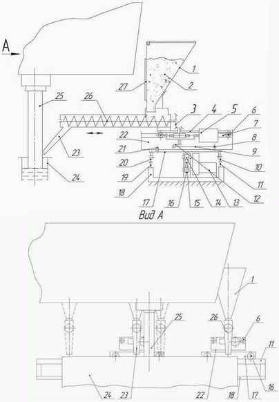
On each trolley still attached feed hopper 1, provided in the lower part of his screw feeder 26 with an inclined feed toe 23. Housing has a screw feeder output tray, which is omitted outlet of the hopper. Dispenser is rigidly fixed on the carriage 4, equipped with two pairs of rollers 6, placed in the guides 7 turret 22 which has the possibility of a fixed rotation on the vertical axis 21 relative to truck 17 with an angle form 30° — 150° to the direction of its movement along the guides 11 and 19.
The carriage 4 together with the pump 26 has the ability to move in the guide 7 on the truck 17 and the hopper 1 at a distance is equal 0,5 of the thickness of the cast slab.
The rotation of the screw feeder 26 provides fixed on its case worm gear motor 5 with a vertically positioned low–speed shaft, the upper shank through which a pair of bevel gear 3 is connected with the screw shank, and at its lower shank mounted crank 12, pivotally connected to the connecting rod 9.
The length of the crank form 0,5 on the magnitude of displacement dispenser 26 relative to the hopper 1 and the second end of the rod with your finger 8 is associated with the turret 22. A hopper on top cover, and in front of his wall is a window 27 to control the level of being in it SFM 2.
The device (figure 3) operates as follows. Before you start casting both a hopper filled with slag–forming mixture of 2 to the specified level by controlling its position through a window 27, then close them. If necessary, carry out setting of the feed socks 23 feeders 26 relatively large near the wall of the mold 24, for which the turrets 22 rotate on axes 21 on the trolleys 17 in the desired angle to the direction of their movement, which must be 0,4 — 0,45 of the slab width, depending on the outside diameter of the submerged nozzle 25, located in the center of the mold 24.
After starting the stream caster, when the level of liquid steel in the mold 24 rises before the mark, at the same time provide start the motor-reducer 13 provides the movement of trucks and gear motors 5 lead screw rotation dispensers 26. At the same time spur gear 14, fixed to the shaft of the gear motor 13, rotates and moves the toothed rack 15 on the support rollers 16 from one extreme to another, and, consequently, the associated truck 17, based his channel wheel 10 and 20 at two guides 11 and 19 of frame 18. When moving trucks at a distance equal to 0,4 — 0,45 of the slab width, is automatically reverse drive and the truck begin to move in the opposite direction. In turn, the rotation of the vertically arranged shaft gear motors 5 through bevel gear pair 3 will be transmitted to the screw feeders 26 and the crank 12, connected to the connecting rods 9. Rotating screw feeders 26 by feeding the slag-forming mixture to the socks 23 from the output tray, where it passes through the exhaust pipes of bunkers 1. Due to the consolidation of the finger 8 rods 9 to turret 22, by rotating crank 12 there is a force of influence through housing gearmotors 5 and feeders 26 on the carriage 4, forcing them to perform reciprocating movement on the rollers 6 in the guide 7 on the turret 22. Together with carriage 4 will reciprocate dispensers 26, and their distance is equal 0,5 of the thickness of the cast slab.
Thus, the oblique feeding socks 23, of which poured into the mold the SFM, will simultaneously participate in two reciprocating motions — relative (with carriages 4) and a laptop (along with the cart 17). Because of this mixture is evenly distributed on the mirror of the metal in each of the two halves of the mold width and length between the narrow faces and submerged glass 25, located in the center of the cross-section of the cast slab. It should also be noted that the proposed kinematics of the mechanical system ensures the implementation of lateral movement and rotation of the dosing screw him with one combo drive, and it is possible to achieve the desired compactness of the assembly as a whole.
Calculation of design and energy-power parameters of the system under consideration dosing SFM holds the following sequence. Was initially determined by the desired performance, size and mass of the dispenser and the carriage on which it is mounted. The results obtained formed the basis for calculating the capacity of the combined electro-mechanical actuator that provides the mechanisms of simultaneous dosing of the SFM and the movement of the carriage. After determining the total (total) mass of each of the two trucks to transport a given speed dispensers about the longitudinal axis of the mold, was their total capacity is designed rack and pinion drive.
Performance dosing was determined taking into account the specific charge of the SFM, which is on the technological conditions of casting metal casters is qр = 0,3 - 0,5 kg/t of steel [6].
Mass flow rate of steel (t/min) in a continuous casting:
where В и h — the width and thickness of the cast slab, m;
ν — speed drawing blanks (casting speed), m/min;
ρc — density of liquid steel, t/m³.
Required mass productivity (kg/min) of each of the two feeders:
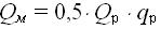
Mass performance screw feeder is expressed in terms of its geometric and velocity parameters, taking into account bulk density fed them the SFM:

where Dш — external diameter of the screw turns, m;
dв — diameter of the screw shaft, m;
tш — step turns the screw, m;
nш — frequency of screw rotation, rot/min;
Ψ — fill factor interturn space auger;
ρшс — bulk density of slag-forming SFM dosage, kg/m³.
This expression is in accordance with the adopted when designing the screw ratio of its major dimensions of dв = (0,35…0,4)×Dш and tш = 0,5×Dш, and fill factor interturn space for SFM Ψ =0,55 takes the form:
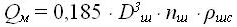
From the outer diameter of the coil screw will be:
Substituting in the formula for given values of bulk density and frequency of dosing SFM screw rotation, define the outer diameter of its turns, and then from the above relations – the other key dimensions that are needed to calculate the energy-power parameters drive dosing.
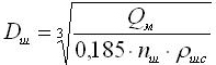
Calculation of the parameters of the combined drive mechanisms dosing mixture and moving the carriage feeder holds, given that the force developed by the drive should be sufficient for simultaneous operation of two mechanisms:
where N1 and N2 — the share of drive power required, respectively, for rotating the screw feeder for moving the carriage mounted with its spout, W;
ηк, ηч and ηкр — efficiency, respectively, bevel gear, worm gear and crank mechanism.
Value of the first component N1 in accordance with the recommendations of [7] can be determined from the sum of the forces of resistance movement Fc SFM tube feeder:
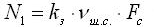
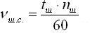
where kз — the safety factor taken equal to 1,15…1,25;
νш.с. — velocity of the SFM, m/sec.
The total drag force Fc takes into account: the friction force the mixture on the bottom of the pipe feeder during its movement, the axial force arising from friction torque turns the screw on the mixture is transported, by the equivalent of the internal friction of the transported mix.
Frictional force SFM to the pipe wall dispenser:
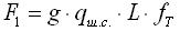
where g — the acceleration of gravity, m/s²
qш.с. — weight of the conveyed mixture per 1 m auger;
L — length of the screw, m;
ƒт — coefficient of friction on the bottom of the SFM tube dispenser.
Axial force arising due to the friction torque turns the screw on the transported SFM:
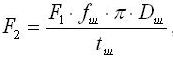
where ƒш — coefficient of friction of the SFM on a screw.
Force, equivalent to the internal friction in the transported SFM:
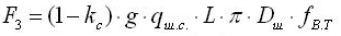
where kс — the rate coefficient equal to the ratio average actual velocity of the mixture to the nominal taken to be equal to the experimental data 0,6...0,7;
L — length of the feed pipe screw feeder, m;
ƒв.т. — coefficient of friction of the mixture.
Travel speed SFM:
The maximum value of the second component of power is given by:
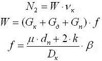
where W — power of resistance movement of the carriage, N
νк — maximum velocity of the carriage, m/sec.
Gк — force of gravity carriage;
Gд — force of gravity feeder with a mixture;
Gп — force of gravity drive;
ƒ — reduced drag coefficient.
μ — coefficient of friction in the bearings of the carriage rollers;
dп — diameter of the bearing, mm;
k — Coefficient of rolling friction, mm;
Dк — diameter of the runner, mm;
β — coefficient taking into account the additional resistance of the friction rollers on the rails.
When calculating the power drive mechanism for moving trucks accounted resistance to their movement in the running flanged wheels:
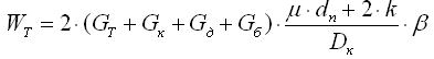
where Gт — force of gravity truck;
Gб — orce of gravity hopper with the mixture.
Then, drive power is:
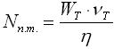
where νт — given the average speed of moving trucks, m/s;
η — the total efficiency of the mechanism.
The optimal values of velocities of the carriage νк and the trolley νт should be determined on the basis of achieving uniform distribution of the SFM over the entire surface of the melt in the mold for the minimum possible number of passes to the metering system along the mold. In this case, there shall be no formation of a so-called slag "cord" around the perimeter of the mold, hang in there shell harvesting and twisting on its surface. Specified requirements are satisfied in the case maintain the desired thickness of the mixture and formed after the fusion of molten slag.
According to [6], the thickness of the slag melt to be at least 2 mm. Using this value as a reference, to determine the relative velocity and the portable metering device, which, respectively, were equal rates of movement of carriages νк and carts νт.
Second volume flow SFM (m³/s):
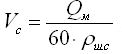
The volume of the slag layer (м³) in each of the halves of the mold:
where S — surface area of metal between the submersible glass and a narrow side face of the mold, m²
δ — the thickness of the slag, m.
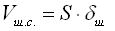
Time interval (s) required for the formation of the mirror metal layer of slag required thickness:

Based on the condition that a given slag layer should be formed in three passes along the dispenser half of the mold, the velocity of the truck will be:
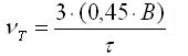
Speed of moving the carriage (m / s) is determined by taking into account the fact that its progress should be half the thickness of the slab, h:
где a — the width of the pickup sock feeder, mm.
Figure 4 shows 3-D model developed by the metering system.
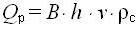
In order to validate the technical solutions proposed by the metering system design and correctness of the calculated data obtained using the above relationships, designed and manufactured its laboratory model (figure 5), in which the testing operation of all control mechanisms and implemented energy-power parameters of their drives.
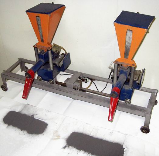
The design of a metering device laboratory sample of the developed system has been provided the ability to install auger with different geometrical characteristics listed in table 1.
| The screw auger | Size of the components screw auger, mm | ||||||||
| Dш | dв | tш | |||||||
| I | 34 | 12 | 12 | ||||||
| II | 48 | 20 | 28 | ||||||
| III | 57 | 22 | 35 | ||||||
| The screw auger | Parameters of the screw auger during the experiment | Mass draw mixture in the experiment, g | Consumption of material, ensure of the metering device in the experiment, g/min |
Calculated value of the mass was issued, g | Calculated consumption of material, ensure of the metering device, g/min | Discrepancy between the experimental and calculated data, % | |||
| Frequentcy of rotation, min-1 | Run time, s | ||||||||
| I | 7 | 20 | 10 | 30 | 9,8 | 29,4 | 2 | ||
| 40 | 19 | 29 | 19,6 | 29,4 | 1 | ||||
| 60 | 32 | 32 | 29,2 | 29,2 | 9 | 15 | 20 | 23 | 69 | 20,9 | 63,7 | 9 |
| 40 | 45 | 68 | 41,9 | 63,4 | 10 | ||||
| 60 | 68 | 68 | 62,9 | 63,9 | 7 | 20 | 20 | 27 | 81 | 27,9 | 84,7 | 4 |
| 40 | 53 | 80 | 55,9 | 84,9 | 5 | ||||
| 60 | 87 | 87 | 83,9 | 84,9 | 3 | ||||
| II | 5,5 | 20 | 34 | 102 | 37,1 | 111,3 | 8 | ||
| 40 | 71 | 106 | 67,8 | 102,7 | 4 | ||||
| 60 | 106 | 106 | 101,6 | 106 | 0 | 11 | 20 | 72 | 216 | 67,8 | 203 | 6 |
| 40 | 152 | 228 | 135,5 | 203 | 11 | ||||
| 60 | 230 | 230 | 203,3 | 209 | 12 | 15 | 20 | 94 | 282 | 92,4 | 277 | 2 |
| 40 | 188 | 282 | 184,8 | 277 | 2 | ||||
| 60 | 287 | 287 | 277,2 | 276 | 3 | ||||
| III | 6 | 20 | 76 | 228 | 66,9 | 201 | 12 | ||
| 40 | 152 | 228 | 133,8 | 201 | 12 | ||||
| 60 | 213 | 213 | 200,6 | 201 | 6 | 10 | 20 | 127 | 387 | 111,5 | 335 | 12 |
| 40 | 250 | 381 | 222,6 | 334 | 12 | ||||
| 60 | 355 | 355 | 334,7 | 334 | 6 | 15 | 20 | 190 | 572 | 167,2 | 501 | 12 |
| 40 | 385 | 570 | 334,9 | 502 | 12 | ||||
| 60 | 519 | 519 | 501,6 | 501 | 3 | ||||
| Terms of casting parameters | Parameters of the metering device | Driving power, kW | |||||||
| Cross section of the slab, mm | Casting rate, m/min |
Specific consumption of the SFM, kg/min | Mass flow of the SFM kg/min | Size of the screw auger, mm | Rotational speed, min-1 | Matched mechanism of the metering device and carriage’s travel | Mechanism of the truck’s travel | ||
| Dш | dв | tш | nш | ||||||
| 2500×350 | 0,7 | 0,4 | 1,71 | 65 | 25 | 32 | 20 | 0,15 | 0,3 |
| 3250×150 | 1,2 | 0,4 | 1,64 | 60 | 20 | 30 | 20 | 0,2 | 0,4 |