SOFT STARTER WITH PULSE VOLTAGE REGULATION AND QUASI-FREQUENCY CONTROL OF INDUCTION MOTOR.
1. INTRODUCTION TO THE PROBLEM
Certain shortcomings of the thyristor softstarters such as motor supply voltage distortion, lag shift angle of the 1st harmonic current, increased energy losses in the induction motor transients can be reduced by the application of pulse voltage regulators (PVR) operated on fully controlled power switches (for example, IGBTs) with certain switching algorithms and high switching frequencies. In case of PVR the regulation of the induction motor supply voltage is carried out by changing the width of voltage pulses, which are cut out from every half-cycle of the voltage waveform at certain switching frequency. As electromechanical properties of induction motors are mostly determined by the first voltage harmonic, it makes sense to control the output voltage of pulse soft starter in the first harmonic magnitude. According to the results of the research introduced in [3] it is recommended to apply exponentially the 1st harmonic voltage variation to obtain optimal energy losses as well as lower PVR output voltage and current harmonics content. For a more detailed comparison of the thyristor and transistor softstarters please refer to [3]. Power circuit of a one phase PVR and its output voltage curve for R and L-load are presented in Fig.1. Such circuit consists of two pairs of inverse-parallel connected transistors T1-T4 with bypass diodes D1-D4 and allows for stator voltage regulation by changing the pulse width at some certain IGBT switching frequency. The first pair of IGBT-transistors (T1 and T2) provides energy flow in both directions (to the load and to the supply mains) while the second pair (T3 and T4) shunts the RL-load when both T1 and T2 are in off state.
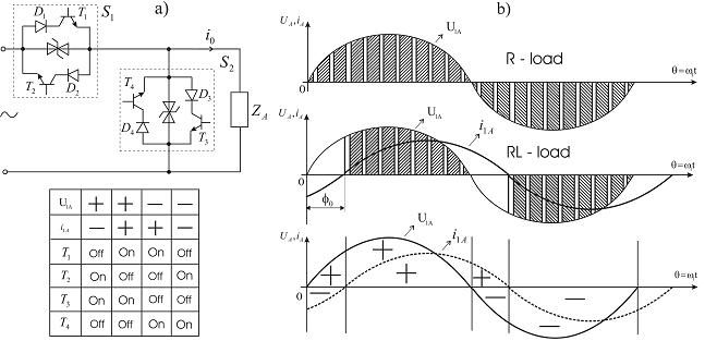
Fig. 1. One phase PVR power circuit (a) with power switches operation table, PVR output voltage curve for R-load and RL-load (b).
Due to such an operation sequence of IGBT-transistors an uninterrupted current flow through the circuit is provided all the time. IGBTs T1-T4 switching sequence depending on the current Ai1 and voltage U1A sign is presented in the table of Fig. 1. For a more detailed information on the one phase PVR operation please refer to [4]. The authors of this paper have performed a comparison of the following three types of power circuits: symmetric power circuit with 6 pairs of switches, PVR with 3 pairs of power switches and a diode shunt bridge, and, finally, a circuit based on 4 pairs of switches with one IGBT-free phase. (Fig. 2).
2. A COMPARISON OF PVR POWER CIRCUIT STRUCTURES Three types of PVR power circuits are presented in Fig. 2.
The most expensive structure of PVR power circuit includes 6 power switches pairs (12 IGBTs in total, Fig. 2a). Such power circuit can be described with the lack of phase currents asymmetry and the simplicity of the control and switching algorithms. When one of the supply mains transistors T1-T7 is switched on, there is an energy exchange going on between the load and the mains. While T1-T7 are in off state, shunt transistors T8-T12 bypass the load phases so that the current could continuously flow though the circuit.
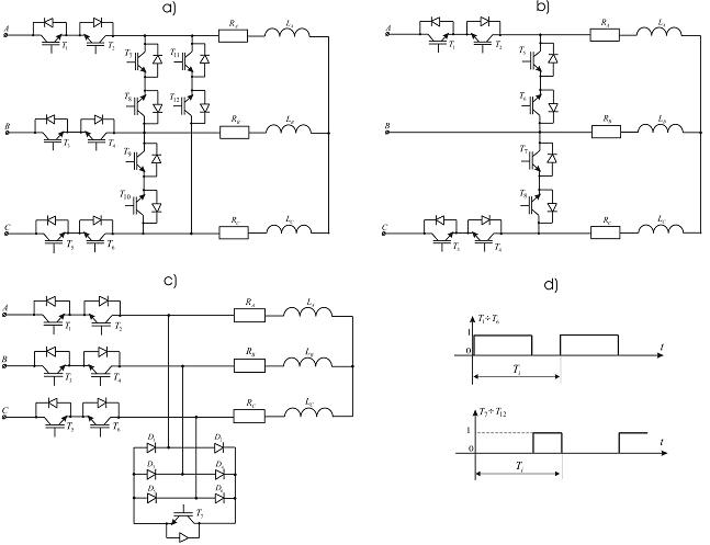
Fig. 2. PVR power circuit with 6 switches (a), 4 power switches (b) and 3 switches with shunt diode bridge (c), mains and shunt switches operation sequence (d).
The second type of PVR power circuit (Fig. 2c) consists of the 3 power switches (6 IGBTs T1-T6), a diode shunt bridge D1-D6 with one unidirectional IGBT T7. The diode bridge with transistor T7 are used for bypassing the RL-load phases while the supply mains transistors T1-T6 are switched off. This type of PVR power circuit has much less phase currents asymmetry and consists of fewer power modules than the first structure hence it is less expensive.
The most cost-effective type of PVR power structure is the one with only 4 power switches. (Fig. 2b) It consists of the 4 supply mains IGBTs T1-T4 and 4 shunt IGBTs T5-T8, while one of the phases remains IGBT-free. The lack of a third power switch in one of the phases results in significant phase currents asymmetry and therefore increased power losses in the induction motor transients. As one of the shortcomings for this type of PVR power circuit one can also mention the uncontrolled induction motor braking time (Fig.4b – 1st speed curve). Therefore, to provide its quicker stopping one should turn off the IGBT-free phase with a contactor during the induction motor braking (Fig.4b – 2nd speed curve).
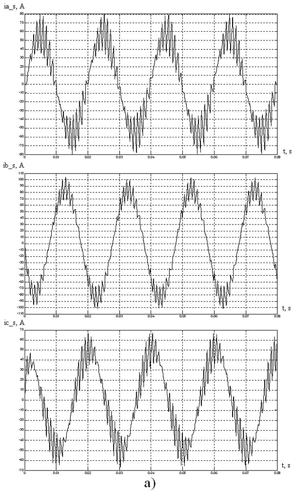

Fig. 3. PVR output currents for the power circuit with 4 switches (a) and 6 switches (b).
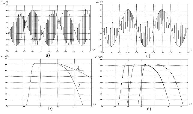
Fig. 4. PVR output voltages and induction motor 4MTKF160LB8 speed curves for the 4 switches (a, b) and 6 switches with (c, d) power circuits.
With the increase of phase currents asymmetry energy losses tend to be higher. Asymmetry of one phase current to another one can be described on percentage basis. The authors of this paper have carried out the analysis of asymmetry degree for the three types of PVR power circuits: 4 power switches circuit, 6 power switches circuit and 3 power switches circuit with shunt diode bridge. The results of phase currents asymmetry calculation are presented in table 1.
Table 1. Phase currents asymmetry and energy losses comparison for various types of PVR power circuits.
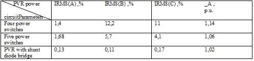
To estimate the asymmetry degree the obtained via simulation phase currents RMS values for each of the three PVR power circuit structures have been compared to the phase current RMS value of the symmetric PVR power circuit with 6 power switches. Also the comparison of energy losses in the induction motor 4MTKF160LB8 (11kW, 380/220V, 40% duty cycle, inertia factor k J = 1.6 ; Tload = Tnom , t 0 = 0,4s ) transients for the symmetric and asymmetric PVR power circuit structures have been performed. It can be seen that the phase currents asymmetry is especially significant for the 4 power switches circuit of PVR, which causes additional energy losses in the induction motor transients and ultimately leads to its longer starting and braking.
3. QUASI-FREQUENCY CONTROL FOR THE INDUCTION MOTOR LOW SPEED OPERATION.
Quasi-frequency control of an induction motor combines to some extent the advantages of parameter and frequency control methods [1, 2]. Quasi-frequency control can be applied for the induction motor operation at low speeds, which is important for positioning mechanisms. For example, it can be used for the electric drives of the crane traveling mechanisms.
The formation of the PVR output voltage curve (phase A) during quasi-frequency control is shown in Fig. 5. According to Fig. 5 the transistors T1, T2 take part in the formation of the PVR output voltage. Supply mains transistors T1 and T2 pass current for the positive and negative quasi-voltage half-waves respectively (time interval t1 ), while T7 operates only as a shunt (time interval t2 ) when either T1 or T2 is in off state so that the circuit current could decrease to zero.
The formation of the induction motor supply voltage consists of a series of positive and negative supply mains voltage half-waves, which are formed according to the alternating-sign switching function U A + and U A - . The sign of this switching function defines quasi voltage polarity while its period Tquasi sets the number of positive and negative supply mains voltage half-waves in it. To obtain the symmetric three-phase supply voltages of certain reduced frequency these switching functions have to be phase-shifted by 1200.
If compared to the thyristor voltage regulator the formation of the quasi voltage curve in case of PVR is performed with a certain switching sequence of the mains and shunt transistors according to the desired quasi frequency. To variate quasi-voltage value one should change the mains transistor and shunt transistor pulse widths. For the induction motor operation at low speed it is imperative to maintain flux linkage at constant level by decreasing the quasi-frequency control voltage proportionally to the reduced frequency. Otherwise, an oversaturation of the induction motor magnetic system will occur.
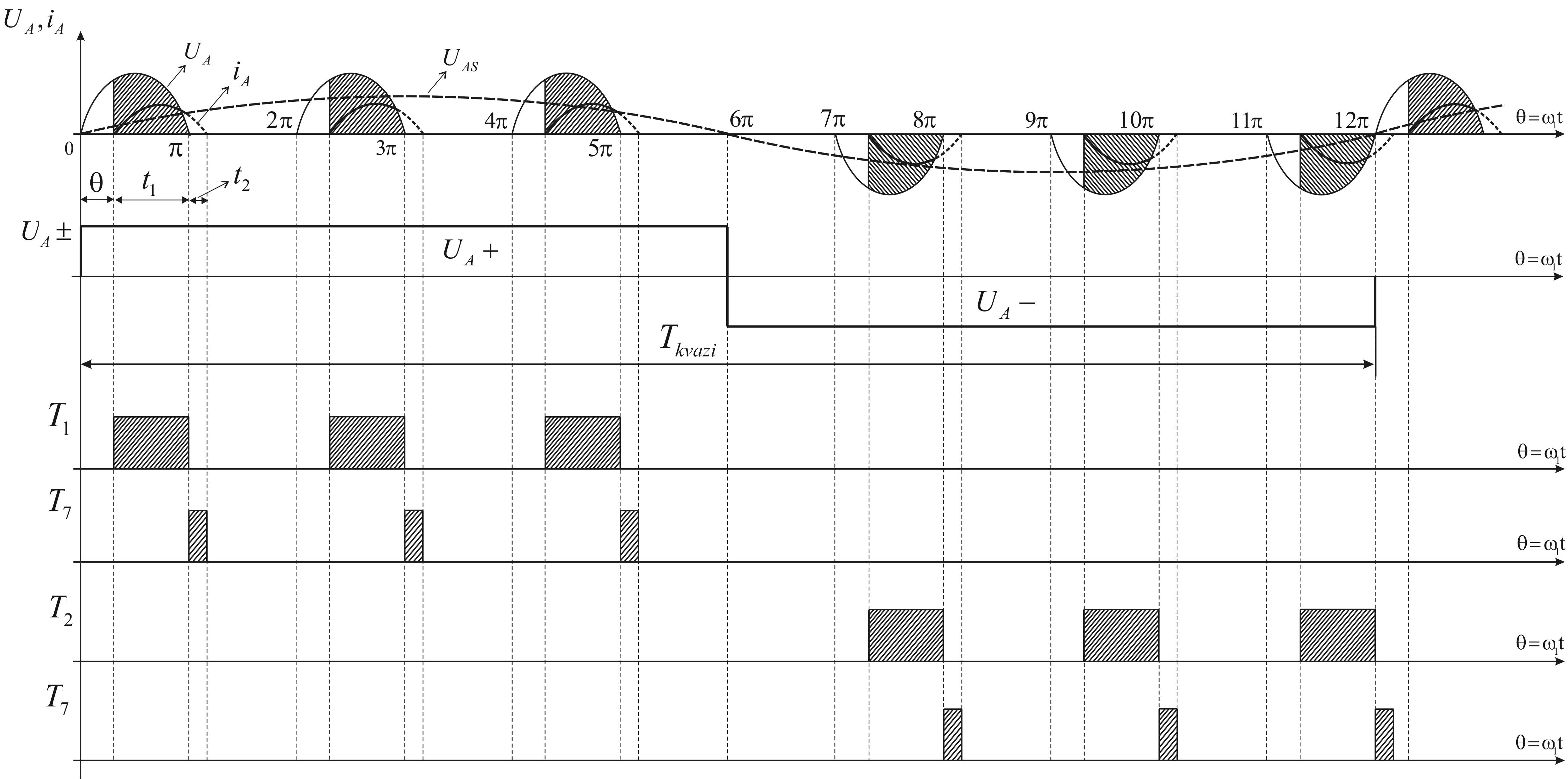
Fig. 5. PVR output voltage and current curve formation during the quasi-frequency control of induction motor (phase A) at 8,33 Hz ( = 0,12 Tquasi ).
The authors have performed simulation of the crane induction motor 4MTKF160LB8 operation at low speed (8,33 Hz quasi-frequency , = 0,12 Tquasi s) for the PVR power circuit with 3 switches and a diode shunt bridge (Fig. 2c). The results of this simulation are presented in Fig. 6 and Fig. 7.
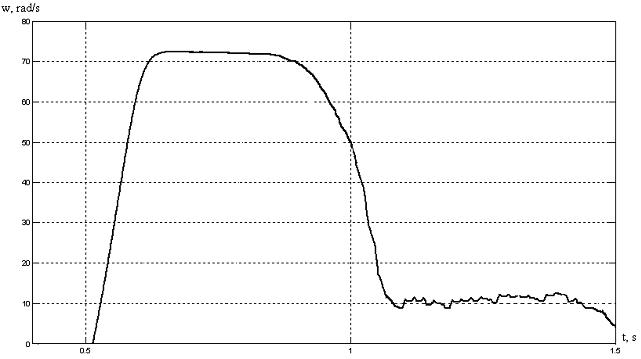
Fig. 6. 4MTKF160LB8 induction motor speed curve with the low speed operation at 8,33 Hz during the quasi-frequency control.
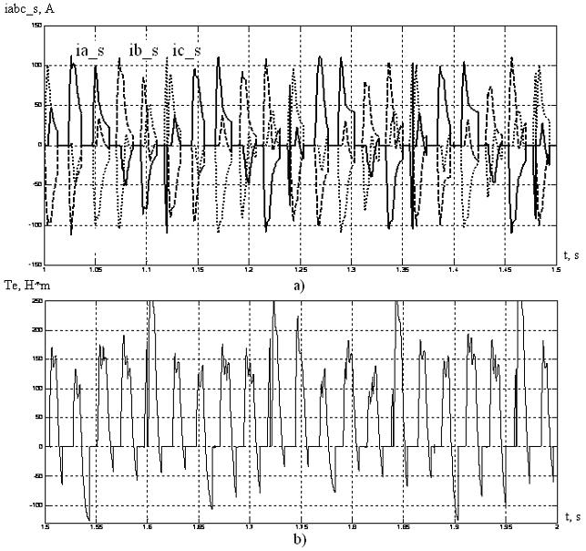
Fig. 7. Three-phase stator current (a) and torque (b) of 4MTKF160LB8 induction motor during quasifrequency control at 8,33 Hz.
In spite of the simplicity of its technical representation quasi-frequency control results in the motor speed fluctuations because of the pulse nature of stator current and motor torque during the quasi-frequency control. PWM control switching to quasifrequency control results in rapid frequency decrease, while the voltage magnitude remains near the same level. This event causes vibration of the induction motor while switching to the low speed operation. The refore quasi-frequency control should be applied to the induction motor low speed operation for a short-term period.
4. CONCLUSIONS
When there are no speed control requirements for a certain technological mechanism pulse voltage regulator has obvious advantages as compared with the phase voltage regulator such as better harmonics content, absence of a lag shift angle in the current waveform, less energy losses, greater number of switching frequency.
The results of this research show that pulse voltage regulator with a power circuit based on 3 power switches and a shunt diode bridge can be considered as a perspective and reasonable replacement for the thyristor softstarter. This relatively inexpensive (if compared to frequency converter) and technologically simple device with quasi-frequency control feature would provide not only the reduced energy losses in transients of induction motor due the its symmetric power circuit structure as well as lowered impact on supply mains but also can be used for the short-term operation of induction motors at low speeds. Such feature can be especially useful for positioning mechanisms, for example, bridge crane trolley traveling mechanism.
REFERENCES
[1] АНДРЮЩЕНКО О., ЛИПАТОВ Г., ХЕРУНЦЕВ П. Исследование режимов асинхронного электропривода при квазичастотном управлении. Электротехническая промышленность. Сер. Электропривод, 1989, вып. 4 (102).
[2] ТИМОФЕЕВ В. Особенности реализации режима циклоконвертирования в системе ТК-АД. – В кн.: Усовершенствование и автоматизация промышленных электроприводов и электроустановок. – Иваново, ИвГУ, 1988, с. 65-70.
[3] FIRAGO B., VASILJEV D., PAWLACZYK L., Zastosowanie impulsowego regulatora napięcia dla miękkiego rozruchu i hamowania silników, Prace Naukowe Instytutu Maszyn, Napędów i Pomiarów Elektrycznych, nr 62, Studia i Materiały nr 28, s. 378-386, Politechnika Wrocławska, Wrocław, 2008.
[4] WINIARSKI B., TUNIA H.. Energoelektronika. Regulatory prądu przemiennego. Wydawnictwa Naukowo-Techniczne, Warszawa, 1994, s. 205 - 215.